
When using the lamp base circuit delay circuit 2

The NE555 timer, configured in a monostable mode, serves as the core of the delay lamp circuit. When either button SB1 or SB2 is pressed, the circuit triggers a pulse that causes the NE555 to output a high signal. This high signal is responsible for energizing the relay K, which in turn closes contact K1 to maintain the circuit's operation and keep the E lamp illuminated. The use of a bridge rectifier (VDL VD4) ensures that the circuit receives a stable DC voltage from an AC source, which is crucial for the reliable operation of the NE555 timer.
The stability of the lamp's illumination is maintained by the voltage divider formed by resistors R, which ensures that the voltage at pin 2 of the NE555 remains above the threshold level required for the timer to continue its output. When the capacitor C charges to approximately 2/3 of the supply voltage, the NE555 transitions back to its low state, deactivating relay K and consequently turning off the E lamp.
This design effectively manages power consumption by utilizing an electromagnetic relay that minimizes energy usage when the lamp is off. The choice of a compact relay, such as the JRX-13F, allows for a space-efficient design while ensuring reliable performance in switching applications. Overall, this NE555 delay lamp circuit is a practical solution for applications requiring delayed lighting with minimal power consumption.Another is the use of money when NE55S delay lamp circuit group circuit, SB1, SH2 are J-light button, can be installed in two different places, the lamp can be operated E. Pres s F SB1 or SB2, the E lamp that is energized to emit light. While alternating purple T Buck, VDL VD4 bridge rectifier in j two ends about 12 DC output voltage. At this point NE55j timebase circuit feet because contacts k 2 closed together is low, the time base circuit is set feet high output, relay K station, which station contact k 1 closed, the gate circuit lock; break contact k-2 tripped due to R, R. Partial pressure foot level stabilization in]/2v m, circuit status will not change, so the E lamp remains lit.
Then power through resistor R. Ask ( electricity crisis, when charged to the supply voltage of 2/3, just reset circuit group, C, store charge quickly through feet to NE555 internal vent tube put q three - cho ready for the next turn on the lights ashamed delay, Meanwhile lemma relay K release, contact k1, k-2 complex position, lamp E goes out. book circuit characteristics after the lights, and then a small circuit consume any power relay K Gallery has adopted two silk small electric shock to convert electromagnetic relays, such as JRX-13F, DC12V type.
Related Circuits
The electronic fishing shrimp machine circuit consists of an astable oscillator, an inverter circuit, and a high-voltage output circuit, as depicted in Figure 20. The astable oscillator circuit includes a time-base integrated circuit (IC), resistors R3 and R4, a...
This switch allows the model train at such a station to automatically slow down. The train stands for a certain amount of time and then slowly pulls back. You do not need to stop the train. The relatively simple...
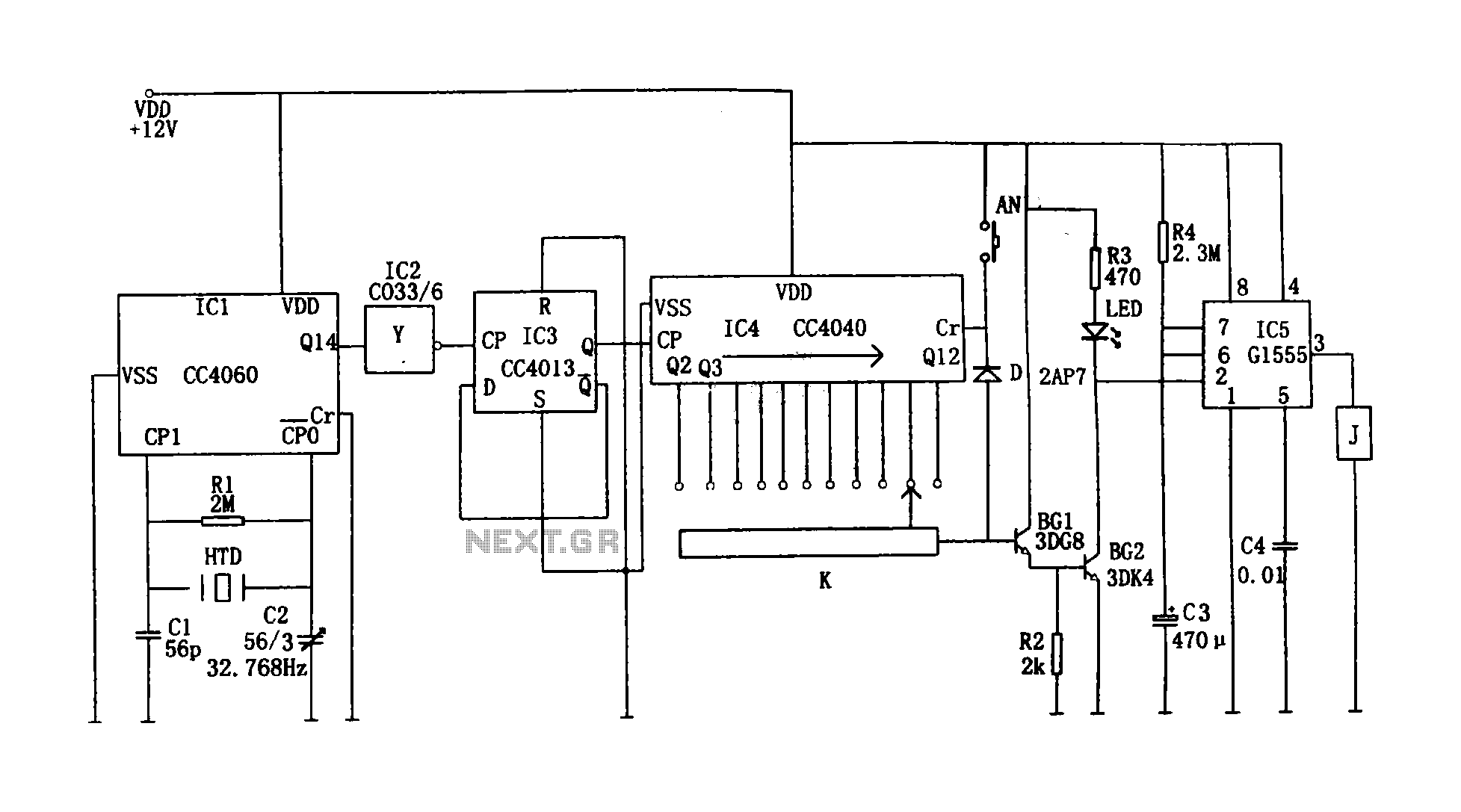
This circuit illustrates a precision digital timing control system. The controller includes a crystal oscillator circuit, a divider, a counting circuit, and monostable flip-flops. The crystal oscillator circuit features a series of 14 binary counters/dividers, a watch crystal operating...
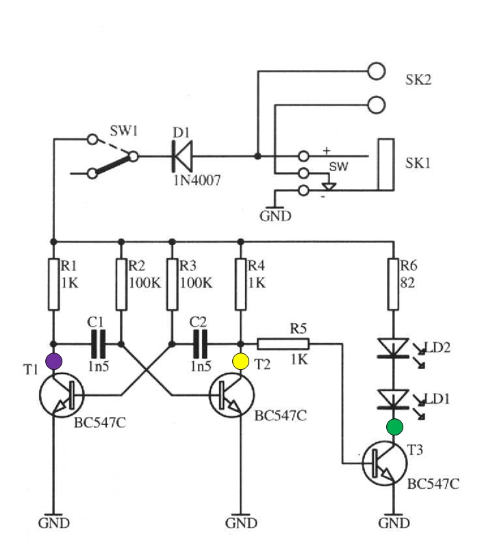
The schematic circuit presented below illustrates an infrared transmitter. The infrared beam is emitted in a nearly line-of-sight manner towards another device equipped with an infrared receiver. The displayed waveforms represent the output voltages from two intermediate stages (purple...
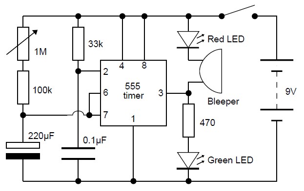
This adjustable analog timer circuit begins timing when it is activated. A green LED illuminates to indicate that the timing is in progress. Upon completion of the set time period, the green LED turns off, a red LED activates,...

This design is likely to generate significant radio frequency interference (RFI) without the incorporation of a choke. The house wiring serves to limit the rate of change of current (di/dt). It is a cost-effective design that demonstrates hysteresis at...