
Rf Output Indicator

The RF detector circuit typically consists of a few key components: a diode, a resistor, a capacitor, and an LED. The diode acts as the primary sensing element, converting the RF signal into a DC voltage. This process is known as rectification. The output from the diode is then filtered using a capacitor, which smooths out the rectified signal, allowing for a stable voltage level that can be used to drive the visual indicator.
In this configuration, the resistor is connected in parallel with the LED to limit the current flowing through it, ensuring that the LED operates within its specified current range. The LED serves as the visual output, illuminating when an RF signal is detected, thus indicating the presence of RF energy.
The circuit can be powered by a low-voltage power supply, and the sensitivity can be adjusted by varying the values of the resistor and capacitor. This RF detector circuit is particularly useful in applications where monitoring RF output is critical, such as in transmitter systems, ensuring that operators can easily determine the operational status of the transmitter through a simple visual cue.
Additionally, the circuit can be enhanced by incorporating a variable gain amplifier to improve sensitivity or by using a microcontroller to process the signal further, providing more detailed information about the RF output. Overall, this RF detector circuit is a practical solution for visual RF signal indication. A simple RF detector circuit using a visual indicator can be useful for an RF output indicator, etc. This circuit was u sed for a transmitter ON indicator.
Related Circuits

How to handle digital input/output (I/O) in AVR microcontrollers is explained using basic programs and circuits to illuminate an LED, generate a stepper motor sequence, read a push-button switch, and implement key debouncing. The handling of digital I/O in AVR...

The circuit indicates two different water temperature trip points by activating LEDs when the specified temperatures are reached. It is built around the LM2904 dual operational amplifier, which is powered by a 12 V automotive system. A thermistor is...

In certain versions of the circuit, the input buffer may be completely absent, while in other versions, the buffer transistors exhibit different biasing configurations or utilize different transistors altogether. Some designs contain significant errors, including biasing issues and incorrect...
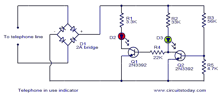
This is a simple circuit designed to function as a telephone status indicator. When the telephone is off-hook (in use), transistor Q1 activates, causing the red LED D2 to illuminate. Conversely, when the telephone is on-hook (not in use),...
This indicator can be used, or see if your speakers can be damaged by the noise power. With P1 you can set the limit to which D1 LED lights. The pot is 100k here, you can even experiment with...
With this circuit can determine whether any of the phones of the same line is busy (it's up the handset), with the help of a LED. The circuit has no measurable effect on the telephone, so that there are...