
Pro Co Rat Input & Output Buffers Guitar

The circuit under discussion involves a configuration where the operational amplifier (LM308) is used in conjunction with symmetrical transistors. The symmetrical nature of the transistors allows for flexibility in their orientation, simplifying the design process. However, the absence of an input buffer in some versions may lead to signal integrity issues, particularly in high-impedance source applications. The output buffer is crucial for driving loads effectively, and its design must account for the output impedance of the LM308 to ensure proper signal transfer.
The biasing of the transistors is critical for optimal performance. If the biasing is incorrect, it can lead to distortion or non-linear behavior, particularly in audio applications such as guitar amplifiers. The use of negative Vgs voltages indicates that the transistors are likely enhancement-mode devices, which require a negative gate voltage to turn off. This design choice can enhance the linearity of the amplifier, but it necessitates careful consideration of the overall circuit design to avoid potential issues with signal clipping or distortion.
In scenarios where the circuit operates without buffers, it is essential to evaluate the load presented by the guitar amplifier and the input impedance of the LM308. A high-impedance load can lead to increased susceptibility to noise and signal degradation, particularly in longer cable runs. Therefore, the design must ensure that the signal path remains robust and that any potential loading effects are mitigated.
Overall, the circuit's performance hinges on the careful selection and biasing of components, the configuration of buffers, and the understanding of the operational amplifier's characteristics. Proper implementation will yield a reliable and high-fidelity audio signal suitable for guitar amplification and other audio applications.In some versions you don`t have the input buffer at all, and in some versions the buffer transistors have different biasing or different transistors. Some have even BIG errors. Errorswith the biasing, errors with the transistor symbols. I understand that the devices are symmetrical, and that means it really doesn`t matter which way you connect the drain and the source.
The second thing that catches my eye is that it seems the devices are supposed to be run with negative Vgs voltages, and that at 0 Vgs, the transistor is fully on. In other words the cut-off voltage Vgsoff is negative. I read somewhere that some guy has made this circuit with different in/out buffers, even with no buffers at all.
It`s looks like the output buffer is more crucial, since in the latter Rat versions the input buffer was discarded anyway. What would the circuit be like without both buffers I guess a guitar amplifier shouldn`t be that big load.
But I guess it influences the LM308 too much 🔗 External reference
Related Circuits
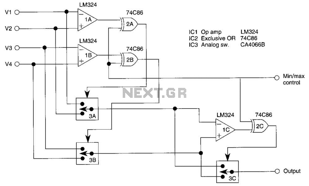
This circuit outputs the maximum or minimum of four input voltages, V1, V2, V3, and V4. Each of these input voltages ranges from 0 to 5 V. The output of the circuit is the maximum of V1, V2, V3,...

A simple yet effective circuit to generate a POTS-compatible ringing voltage can be constructed using National Semiconductor's LM4871 audio amplifier IC along with a dozen passive components. This circuit produces a sine-wave output of 1 W at approximately 70...
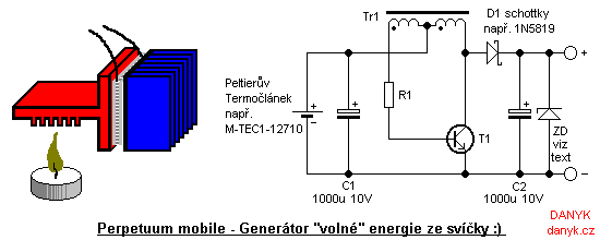
Introduction: This device is not a true perpetual motion machine or a source of free energy from the atmosphere; however, it presents an intriguing experiment, particularly for beginners and enthusiasts of alternative energy sources. It enables the generation of...
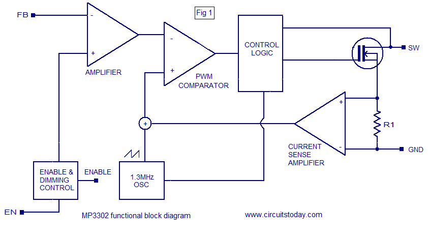
The MP3302 is a boost converter integrated circuit (IC) specifically designed for LED drive applications. It is capable of driving 27 LEDs, arranged as 9 strings of 3 white LEDs in series, powered by a lithium-ion battery. The IC...
This circuit generates a stable 1 kHz sine wave using an inverted Wien bridge configuration composed of components C1, R3, C2, and R4. It features a variable output, low distortion, and low output impedance to ensure good overload capability....
This project originated from the need to control home heating remotely from work. Utilizing a VPN connection between work and home, a relay controlled by a PC was considered the simplest solution. However, a control unit that could be...