
RF Remote Control With HT12E IC

The RF Remote Control Circuit employs the HT12E integrated circuit, which functions as a decoder for the incoming signals. The circuit operates within the 433 MHz frequency band, utilizing Amplitude Shift Keying (ASK) modulation for effective communication between the transmitter and receiver modules. The transmitter module sends encoded data, which is received by the RF receiver module connected to the HT12E.
The HT12E IC is designed to handle parallel data input, making it suitable for applications requiring multiple control signals. Upon receiving the RF signal, the HT12E decodes the data and outputs it in parallel format. This allows for straightforward interfacing with other components such as motors or switches, enabling control of various devices remotely.
The circuit typically includes an RF transmitter module that transmits the data signals, while the RF receiver module captures these signals and forwards them to the HT12E. The components involved in the circuit, such as the switch and motor, can be activated or controlled based on the decoded signals from the HT12E. This setup is ideal for remote control applications, where users can operate devices from a distance with minimal complexity.
Overall, the RF Remote Control Circuit utilizing the HT12E IC exemplifies a practical implementation of RF communication technology, facilitating efficient control of electronic devices through wireless transmission.The following circuit shows a RF Remote Control Circuit Diagram. This circuit based on the HT12E IC. Features: original data in the parallel format, decoder IC receives the signal via the RF receiver module, using ASK (Amplitude Shift Keying) based Tx/Rx (transmitter/receiver) pair operating at 433 MHz, RF transmitter module. Componen t: IC, Switch, Motor. [botskool. com] 🔗 External reference
Related Circuits
This tutorial explains how to read the content of a microcontroller's flash memory. The source microcontroller reads the memory content and displays it on the LEDs. The content consists of the program stored in the microcontroller's memory. This step...
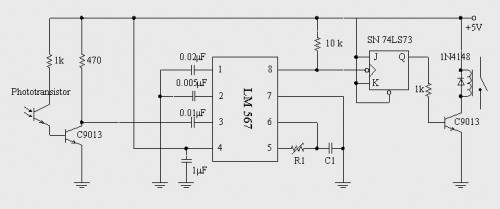
Here is a handy gadget for testing of infrared (IR) based remote control transmitters used for TVs and VCRs etc. The IR signals from a remote control transmitter are sensed by the IR sensor module in the tester and...
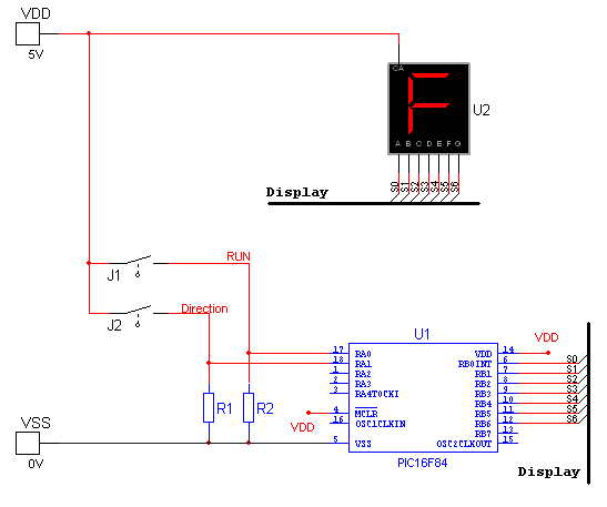
National Instruments Multisim now features microcontroller unit co-simulation capabilities, enabling the inclusion of a microcontroller, programmed in assembly or C code, within SPICE-modeled circuits. The MCU functionality in Multisim allows students, educators, and professional users to program MCUs in...
A simple circuit diagram illustrates a schematic for a remote control system, which consists of two parts: the transmitter and the receiver. The transmitter circuit is controlled by an NE555 integrated circuit (IC) and operates by detecting the emitted...
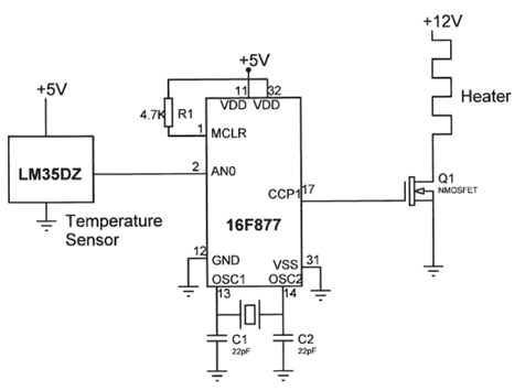
The electrical circuit diagram of this temperature control circuit consists of a 3-pin analog temperature sensor (LM35DZ), a built-in A/D converter microcontroller (PIC16F877), and the heater driver (IRL1004). The temperature control circuit utilizes the LM35DZ, a precision analog temperature sensor...
AVC - The circuit regulates the volume line automatically, providing an output voltage of approximately 4 volts peak to peak. This voltage remains consistent. The Automatic Volume Control (AVC) circuit is designed to manage audio levels dynamically, ensuring a stable...