
TV transmitter circuit using only 2 transistors operates from 12V

The described circuit utilizes two transistors to create a basic television transmission system capable of operating on a 12V power supply. The design is suitable for transmitting signals compatible with PAL B and PAL G television broadcasting standards, which are widely used in various regions.
The circuit typically consists of a pair of bipolar junction transistors (BJTs) configured to amplify the video signal. The first transistor acts as a modulator, where the input video signal is combined with a carrier frequency generated by an oscillator circuit. This modulation process allows the video signal to be transmitted over the airwaves.
The second transistor functions as a power amplifier, boosting the modulated signal to a level suitable for transmission. An LC circuit, composed of inductors and capacitors, is often included to filter and tune the output frequency to ensure compliance with the desired broadcasting standards. The output stage may also include an antenna, which radiates the amplified signal.
To ensure stable operation, proper biasing of the transistors is essential, often achieved through resistors connected to the base terminals. Additionally, decoupling capacitors can be employed to minimize noise and improve the overall performance of the circuit.
It is important to consider the layout of the circuit to minimize interference and maximize signal integrity. Shielding may be necessary to prevent unwanted pickup of signals, especially in environments with high electromagnetic interference.
This simple two-transistor TV transmitter circuit serves as an educational tool for understanding the fundamentals of television transmission and modulation techniques, while also providing a practical application for hobbyists interested in electronics and broadcasting.Simple two transistor TV transmitter circuit that operates from 12V.Compatible with PAL B and PAL G systems.. 🔗 External reference
Related Circuits
This characterization circuit, along with a PC and specific software, accurately measures the complete discharge cycle of a rechargeable AA cell. The capacity and output resistance of the cell can be easily determined from the resulting curve of these...
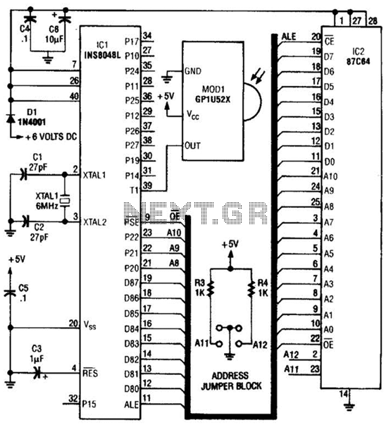
This circuit is based on the Sharp GP1U52X infrared module and the 1NS8048L microprocessor. The GP1U52X is a hybrid integrated circuit and infrared detector that provides a strong, clean signal for subsequent filtering and demodulation. The circuit utilizes the Sharp...
A drink mixer inspired by BAR2D2 utilizes a gravity-fed pump that operates on a 9V battery. The circuit incorporates a 555 timer to control the duration of the pump's operation. When connected directly to the battery, the pump functions...
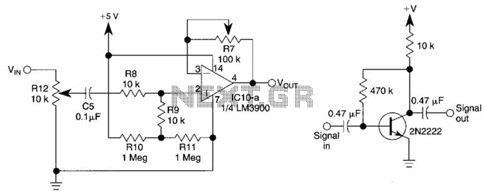
This circuit utilizes one-quarter of an LM3900 to create a simple variable-gain front end for an oscilloscope. R7 serves as the gain control. Additionally, a basic preamplifier is included for applications requiring more than 10X gain. The circuit employs the...
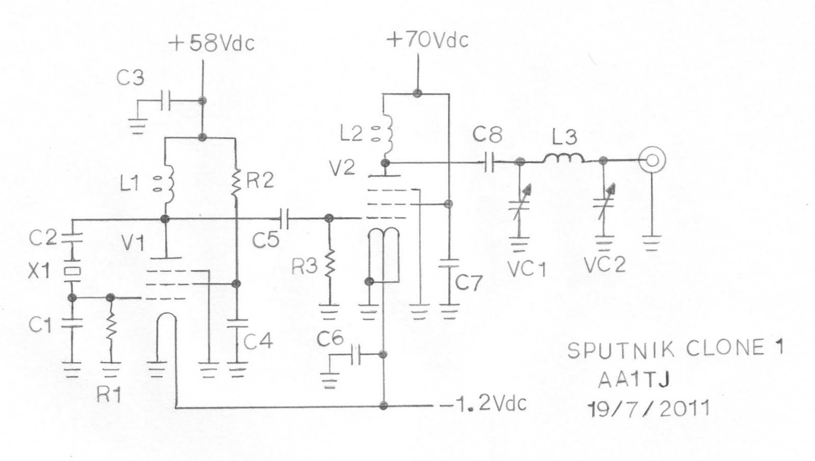
This document describes a prototype transmitter for the Sputnik QSO Party. The RF output power is 450 mW, with 70 V DC at 14.4 mA on the V2 anode. The screen current (G2) for V2 is 1.6 mA, while...
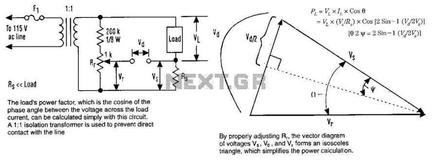
The load's power factor, defined as the cosine of the phase angle between the voltage across the load and the load current, can be calculated using this circuit. An isolation transformer with a 1:1 ratio is employed to prevent...