
tv transmitter

The described transmitter circuit is designed to operate effectively within the VHF (Very High Frequency) and VLF (Very Low Frequency) ranges, specifically targeting the frequency spectrum used by television broadcasts. The circuit's primary function is to modulate audio signals onto carrier frequencies that fall within the specified range of 54 to 216 MHz. This frequency range is crucial for ensuring compatibility with various television systems, particularly in regions employing the PAL System B and PAL System G formats, which are prevalent in several countries.
The modulation process is achieved through frequency modulation (FM), which is a technique that conveys information over a carrier wave by varying its frequency. This method is particularly advantageous for audio transmission, as it provides improved resistance to noise and interference compared to amplitude modulation (AM). The circuit's ability to tune the frequency of the modulated sound signal between 5.5 and 6 MHz is facilitated by the variable capacitor C5. By adjusting C5, the user can fine-tune the transmitter's output to ensure optimal performance and compliance with local broadcasting regulations.
It is important to note that while the circuit has been validated for VHF and VLF ranges, it has not been tested for UHF (Ultra High Frequency) applications. This limitation may affect its versatility in regions where UHF frequencies are predominantly used for television broadcasting. Overall, the transmitter circuit is a specialized device tailored for specific broadcasting standards and frequency ranges, making it a valuable tool for applications within compatible regions.Notes: The frequency of the transmitter lies within VHF and VLF range on the TV channel, however this circuit has not been tested at UHF frequencies. The modulated sound signal contains 5. 5 -6MHz by tuning C5. Sound modulation is FM and is compatible with UK System I sound. The transmitter however is working at VHF frequencies between 54 and 216MH z and therefore compatible only with countries using Pal System B and Pal System G. 🔗 External reference
Related Circuits
An infrared (IR) transmitter-receiver system is being developed to send signals to a device, specifically a simple blue LED. The proposed infrared transmitter-receiver system consists of two main components: the IR transmitter and the IR receiver. The transmitter will emit...
A low-power two-stage FET transmitter designed for the 80-meter amateur band utilizes a Pierce crystal oscillator that does not require an output resonant circuit. A DC milliammeter can be connected across a 150-ohm resistor in the gate circuit of...
1-Transistor FM Transmitter. R1 27k, R2 56k, R3 12k, R4 100, C1 1u, C2, C3 470p, C4 6 to 10p, C5 1-30p trimmer, L1 etched on PCB. The 1-transistor FM transmitter is a compact electronic circuit designed to transmit audio...
This oscillator is known as the Colpitts oscillator and is voltage-controlled to facilitate frequency modulation (FM) and phase-locked loop (PLL) control. The transistor T1 should be a high-frequency (HF) transistor for optimal performance; however, in this instance, a common...
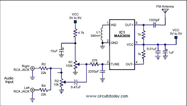
A simple single-chip FM transmitter circuit with a diagram and schematic using the IC MAX 2606, which is a high-performance voltage-controlled oscillator (VCO). The FM transmitter circuit utilizing the MAX 2606 is designed for efficient frequency modulation of audio signals....
The following circuit illustrates an FM transmitter circuit diagram operating within the 88-108 MHz frequency range. Features include a 1W transmitter of the Tetsuo style. Components involved are capacitors, among others. The FM transmitter circuit operates in the VHF band,...