
Narrow band FM demodulator

The XR-J567 is a specialized integrated circuit designed for FM demodulation applications, particularly effective in scenarios where the bandwidth is limited to less than 10% of the carrier frequency. Its primary function is to ascertain the presence of a carrier signal, which is critical for maintaining the integrity of the demodulated output. When the XR-J567 detects the absence of a carrier signal, it generates an output that disables the FM demodulator, effectively functioning as a squelch circuit. This feature is particularly useful in reducing unwanted noise during periods of signal absence, thus enhancing overall audio quality.
The XR-215 FM demodulator is employed in conjunction with the XR-J567 due to its exceptional performance characteristics. It boasts a wide dynamic range, allowing it to handle a variety of signal strengths without distortion. Additionally, the high signal-to-noise ratio of the XR-215 ensures that the demodulated signal remains clear and intelligible, even in the presence of background noise. The low distortion characteristic of this demodulator further contributes to the fidelity of the audio output, making it suitable for high-quality FM broadcasting applications.
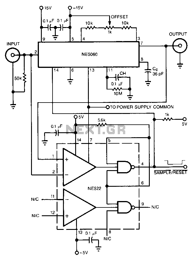
The XR-567 is capable of detecting carriers at frequencies up to 500 kHz, which encompasses a substantial range of FM broadcasting frequencies. The integration of the XR-J567 and XR-215 in a single circuit provides a robust solution for FM demodulation, ensuring reliable operation and high-quality audio output in various communication and broadcasting applications. This combination is ideal for environments where signal integrity is paramount, and unwanted noise must be minimized.For FM demodulation applications where the bandwidth is less than 10% of the carrier frequency, an XR-J567 can be used to detect the presence of the carrier signal. The output of the XR-567 is used to turn off the FM demodulator when no carrier is present, thus acting as a squelch.
In the circuit shown, an XR-215 FM demodulator is used because of its wide dynamic range, high signal/noise ratio and low distortion. The XR-567 will detect the presence of a carrier at frequencies up to 500 kHz.
Related Circuits
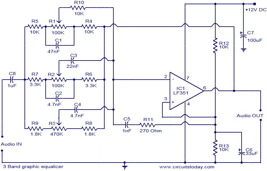
This document presents the circuit diagram of a simple three-band graphic equalizer that utilizes a single integrated circuit (IC) and a few additional components. The IC employed in this design is the LF351, which is a wide bandwidth single...

The circuit described uses a single chip, IC BA3812L, to realize a 5 band graphic equalizer intended for use in hi-fi audio systems. The BA3812L is a five-point graphic equalizer that integrates all the necessary functions onto one IC. The...
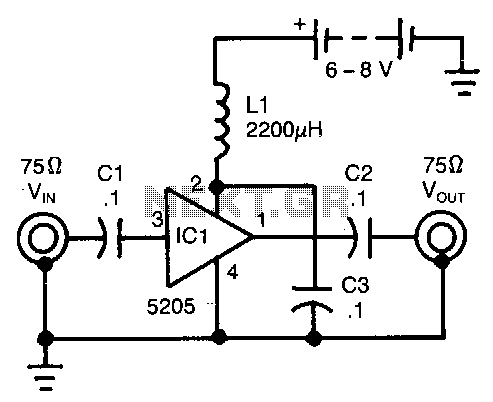
This wideband amplifier utilizes only five components. External signals are introduced to pin 3 of IC1 through an AC coupling capacitor, C1. After amplification, the enhanced signals from pin 1 of IC1 are transmitted to the output via capacitor...
A simple, low component count phase locked loop that locks onto and detects the amplitude of an incoming baseband 7 bit Barker code using a switched resistor demodulator that is driven directly by a microcontroller's output pins. Balanced modulators...
The high-speed peak detector utilizes a highly accurate, fast sample-and-hold (s/h) amplifier that is controlled by a high-speed comparator. The s/h amplifier retains the peak voltage until the comparator switches the amplifier to its sample mode to capture a...

This circuit is a Phase-Locked Loop (PLL) system designed for use as an FM demodulator. The output of the Voltage-Controlled Oscillator (VCO) follows the FM signal, with the input voltage to the VCO being proportional to its output frequency....