
PLL 1 Watt FM transmitter
This FM transmitter circuit is designed to provide a compact and efficient means of transmitting audio signals over a short range. The device operates in the FM frequency range of 87.5 to 108 MHz, making it suitable for personal broadcasting applications. The power output can be adjusted between two levels, 1 W for higher range and 0.2 W for lower range, allowing flexibility depending on the application and regulatory requirements.
The circuit is structured into three main sections: the RF section, the Phase-Locked Loop (PLL) section, and the audio section. The RF section is responsible for generating the radio frequency signal, utilizing components such as transistors and capacitors to create stable oscillations at the desired frequency. The PLL section ensures that the transmitter can lock onto a specific frequency, providing precise tuning capabilities. This is particularly important for minimizing interference with other radio stations and ensuring clear audio transmission.
The audio section includes a microphone amplifier and modulation circuitry, allowing for the input of audio signals from various sources, including microphones and line inputs. The modulation type used is wide-band FM, which provides better sound quality and less distortion compared to narrow-band FM.
The circuit board is designed to accommodate all components in a compact layout, with dimensions of 11.3 x 8.8 cm. The use of a 12 V power supply, either from an accumulator or a regulated source, ensures adequate power for operation, with current consumption varying based on the selected RF power output.
For assembly, the parts list includes a variety of resistors, capacitors, and semiconductors, each selected for their specific roles within the circuit. Notably, the use of trimmer capacitors allows for fine-tuning of the circuit parameters, ensuring optimal performance. The inclusion of connectors for audio input, antenna connection, and power supply facilitates ease of use and integration into various setups.
Overall, this FM transmitter circuit provides a comprehensive solution for personal audio broadcasting, combining essential features in a compact design suitable for hobbyists and engineers alike.This small FM transmitter includes a limiter, a microphone amplifier and a PLL digital tuning. All the parts are placed on one circuit board. The RF power is switchable between 1 W (HI) and 0,2 W (LO). Technical specifications: Supply voltage: 12 V from accumulator or regulated power supply. Supply current (HI/LO): 270/170 mA. RF power HI: 1 W. RF power LO: 0,2 W. Impedance: 50-75 ohm. Frequency range: 87,5-108 MHz. Modulation type: wide-band FM. Modulation inputs: line, mic, RDS/MPX. PCB dimensions: 11,3 x 8,8 cm. The schematic diagram is divided into three parts: RF part (numbered from 1), PLL (numbered from 30) and audio part (numbered from 50). Connect a 6 V / 0,1 A bulb to the output and set the right frequency on PLL. Set the RF power to HI. Now turn on the transmitter. You should tune it on a receiver. Maybe you might stretch coils of the L1. Fix the L1 in position when the tuning voltage (on Q3) is in range 4-9 V. Then use C15, C16 and C17 to adjust the highest power (the highest light of the bulb). Then you can connect antenna and audio signal. Adjust R1 until the audio sounds as loud as the other stations. Complete parts list Resistors: 1x 10 1x 47 1x 100 1x 270 2x 220 3x 470 1x 820 5x 1k 1x 1,5 k 1x 4,7 k 9x 10 k 3x 22 k 3x 27 k 1x 56 k 1x 47 k 1x 180 k 1x 240 k 1x 10 M 3x pot.
5 k log. Capacitors: 1x 8,2 pF 2x 10 pF 3x 22 pF 5x 100 pF 8x 1 nF 1x 1 nF plastic 2x 2,2 nF 5x 10 nF 2x 47 nF 4x 100 nF mini 1x 150 nF 1x 0,47 uF 2x 1 uF 2x 2,2 uF 1x 4,7 uF 4x 10 uF 1x 47 uF 1x 100 uF 1x 220 uF 2x 470 uF 2x 1 uF tantal 1x 10 uF tantal 1x trimmer 47 pF 2x trimmer 60 pF Semiconductors: 1x BC547C (BC548C, BC547B) 1x BFR91A 1x BFR96 1x 2SC1971 1x BC556B 1x BF245C 2x LM386 1x SAA1057 1x PIC16F84A-04 + socket 1x 78L05 1x Yellow LED 3 mm 2x BB109G, BBY31 or BB409 Misc: 1x 4 MHz crystal 2x switch 1x button 1x jumpers 2x8 pins or DIP switches 1x power supply connector 3x jack 3,5 mm 1x antenne connector 1x plastic case thin shielded cables 🔗 External reference
Related Circuits
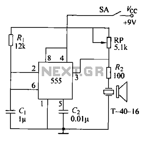
The circuit comprises an ultrasonic transmitter and a T-4 0-16 555 timer circuit. By adjusting the potentiometer RP, the frequency of the oscillation circuit can be modified. The circuit emits ultrasonic signals at a frequency of 40 kHz, with...
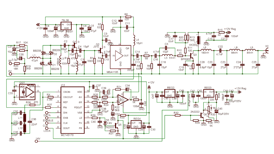
In order to simplify the transmitter design, we've used the new pll circuit from Motorola: the MC145170. This PLL includes the prescaler and a serial standard bus called SPI. We advise to use the P2 version that fixes some...
This low-cost short-wave transmitter is tunable from 10 to 15 MHz using a ½J gang condenser (VC1), which determines the carrier frequency in conjunction with inductor L1. Frequency trimming is achieved with VC2. The carrier signal is amplified by...
Bridged resistive sensing elements are commonly used in resistive type sensors and transducers. This type of sensor requires a biasing voltage to operate. The LM10 provides low... Bridged resistive sensing elements are integral components in various resistive sensors and transducers,...
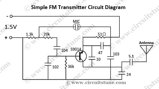
This is a simple FM transmitter circuit schematic diagram that utilizes a single transistor, S9014. The FM transmitter circuit operates by modulating an audio signal onto a carrier frequency, which is typically in the FM band. The S9014 transistor serves...
This simple amplifier can be used for many things. Together with Equalization and (small) speakers good for the computer instance. The circuit uses IC TDA 2003 amplifier. This IC is in a TO-220 housing, and has 5 pins. Decoupling...