
By the UCM-40-T and 74LS00 ultrasonic transmitter circuit consisting of NAND gate b

The ultrasonic transmitter circuit utilizes a T-4 0-16 timer configured in astable mode to generate a square wave output at a frequency of 40 kHz. The 555 timer is a versatile integrated circuit widely used in timer, delay, pulse generation, and oscillator applications. In this configuration, the frequency of oscillation can be adjusted by varying the resistance of the potentiometer RP, which is part of the timing network along with a capacitor connected to the discharge pin of the 555 timer.
The output from the timer drives a transducer that converts the electrical signal into ultrasonic sound waves. The operating voltage of the circuit is set at 9V, which is supplied by a suitable power source. The current consumption of the circuit ranges from 40 mA to 45 mA, ensuring efficient operation while providing sufficient power to the ultrasonic transducer.
The effective control distance of the emitted ultrasonic signals is more than 8 meters, allowing for applications such as distance measurement, obstacle detection, or even in pest repellent systems. The design of the circuit is compact and can be easily integrated into various electronic projects requiring ultrasonic sensing capabilities. The choice of components, including the 555 timer and the ultrasonic transducer, ensures reliability and performance in the intended applications. Circuit consists of an ultrasonic transmitter and T-4 0-16 555 circuit, adjust the potentiometer RP can change the oscillation circuit frequency. 40k 3 feet from the output 555 of azelaic z} oscillating pulse-driven T-4 0-16 work, so that emit ultrasonic signals of 40kHz. Circuit operating voltage of 9V. Operating current 40 ~ 45mA, control distance is more than 8m.
Related Circuits
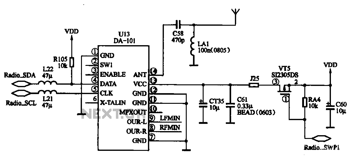
FM radio chip circuits operate differently, as illustrated by the DA-101 chip FM radio circuit. In this configuration, the FM radio broadcast program is received through the headset jack, which functions as an antenna. The signal captured by the...
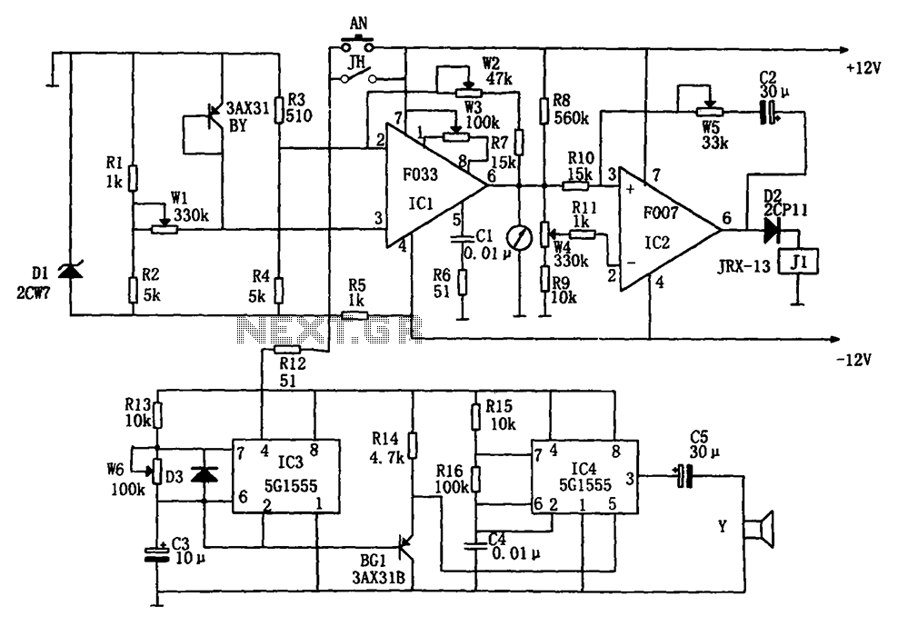
The temperature alarm circuit shown in the figure consists of an inverting amplifier (IC1), a comparison amplifier (IC2), a low-frequency multivibrator (IC3), a controllable oscillation frequency multivibrator (IC4), a bridge measurement network, a speaker (Y), and a power supply...
Acoustic check of transistor and diode junctions. Also suitable as a continuity tester. Short circuits or broken PCB tracks can be easily recognized. The acoustic check of transistor and diode junctions is a method used to assess the functionality of...
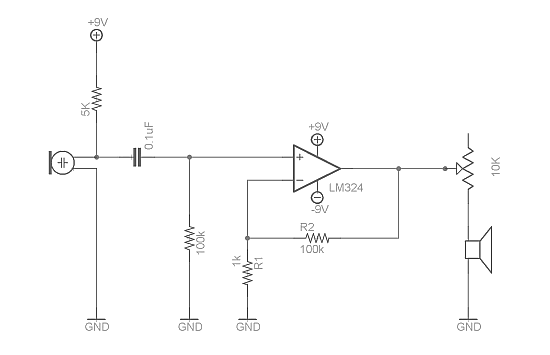
Afroman discusses the fundamentals of utilizing an operational amplifier to amplify small voltage signals and constructs a circuit designed to detect very faint sounds using a microphone. For further details about amplifiers, it is recommended to search for inverting...

The VU meter is categorized into two types: those that use needle instruments and those that employ LED columns. A VU meter sound level meter is essential for both tube amplifiers and integrated amplifiers. Currently, there are numerous integrated...
This circuit is designed to indicate when room noise exceeds a predetermined threshold, utilizing a flashing LED to signal this condition. Three fixed noise levels are selectable: 50 dB, 70 dB, and 85 dB. The circuit employs two operational...