
FM Transmitter with PLL
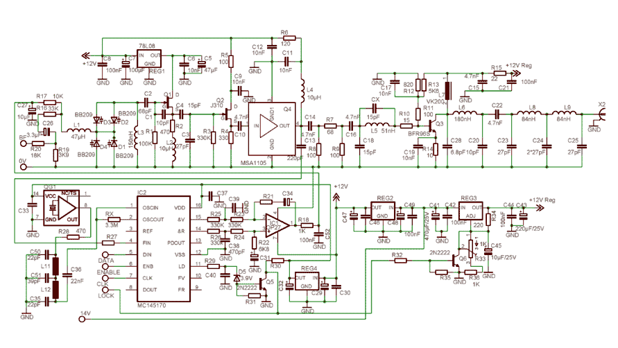
The described circuit employs the MC145170 PLL from Motorola, which integrates a prescaler and an SPI bus for enhanced control and flexibility. The recommendation to utilize the P2 version addresses initialization issues, ensuring reliable performance during power-up. The compact design of the MC145170 allows for a streamlined layout on the radio board, facilitating the integration of a power control circuit that activates the RF signal once the lock detect condition is met.
The LM317 voltage regulator is employed to supply power to the final RF stage, with the output regulated by the lock detect signal connected to its ADJ pin. This configuration ensures that RF transmission only occurs when the PLL is locked, thus improving signal integrity and reducing potential interference.
The oscillator and RF driver stages have been optimized to achieve superior harmonic rejection, enhancing overall performance compared to previous iterations. The substitution of BB204 varactors with BB209 components further contributes to improved tuning characteristics and stability across the FM band.
Key performance specifications include a power output of 200mW, adjustable within the specified range, and a frequency output spanning from 87.5 MHz to 108 MHz, with a frequency step of 10 kHz. The phase noise is rated at -102 dBc/Hz, and the frequency stability is maintained within +/- 300 Hz, ensuring a consistent and reliable transmission. Harmonic filtering is effective at <-60 dBc, while spurious emissions are minimized to <-70 dBc, indicating a well-designed circuit with low unwanted signals.
The inclusion of a Cauer filter enhances second harmonic rejection, further refining the output signal quality. The modulation scheme employed is direct frequency modulation, with an MPX input response maintaining a tolerance of +/- 0.5 dB across a frequency range of 30 Hz to 80 kHz. The minimum MPX input level is specified at 300 mV RMS, providing adequate sensitivity for input signals. The circuit operates with a power supply requirement ranging from 14V to 18V, allowing for compatibility with various power sources while ensuring optimal performance.In order to simplify the transmitter design, we've used the new pll circuit from Motorola :the MC145170. This PLL includes the prescaler and a serial standard bus called SPI. We advise to use the P2 version that fixes some init issues during the Power Up. This PLL circuit is definitely smaller than the old one, consequently we've added on the radio board, the power control circuit that allows to switch on, the RF signal when the lock detect is established.
In fact a simple LM317 that supplies the last RF stage, is controled by the lock detect signal through the ADJ pin. The oscillator and the RF driver stages have been improved to get a better harmonics rejection than the previous version.
We have replaced the BB204 varactors by new ones: BB209. Power Output 200mW ajustable Frequency Output 87.5MHz to 108 MHz Frequency Step 10KHz Phase Noise -102dBc/Hz Frequency Stability +/- 300Hz Harmonic Filtering <-60dBc Spurious Emissions <-70dBc Consequently, the kvco is more stable on the FM band and the AF signal has been directly applied on the control voltage line coming from the pll. A Cauer filter has been added to improve the second harmonic rejection. Modulation Direct Frequency Modulation MPX Input Response +/-0.5dB 30Hz to 80KHz MPX Input Level 300mV RMS Min Power Supply 14 to18V
🔗 External reference
Related Circuits
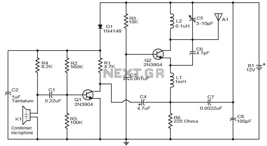
This circuit features a very stable and simple FM transmitter design. This transmitter can achieve a range of approximately 200 meters when properly matched. The FM transmitter circuit typically consists of several key components: an oscillator, modulator, amplifier, and antenna....

The FM transmitter is relatively simple to build and requires only one adjustment, making it ideal for beginners. It is important to clarify that, with wide-band deviation, the Voltage Controlled Oscillator (VCO) is never locked in phase, only in...
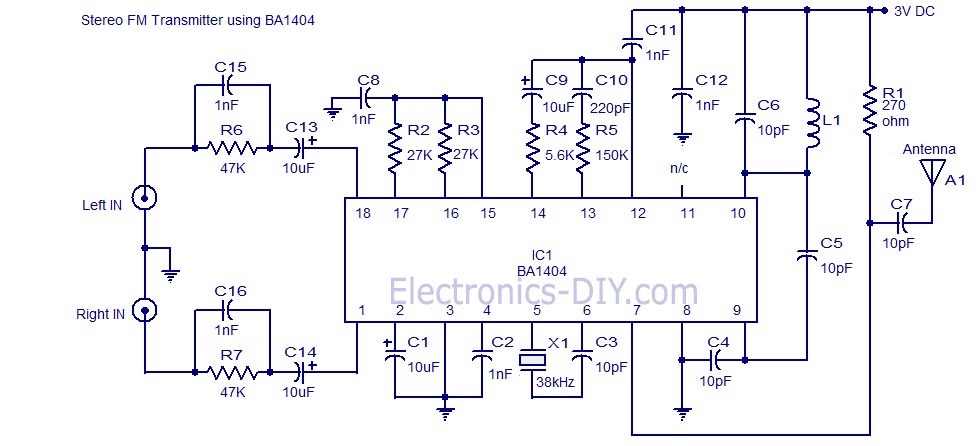
A high-quality stereo FM transmitter circuit is presented. This circuit utilizes the BA1404 integrated circuit from ROHM Semiconductors. The BA1404 is a monolithic FM stereo modulator that includes a built-in stereo modulator, FM modulator, and RF amplifier. The FM...
The circuit of the transmitter is shown in Figure 1, and as you can see it is quite simple. The first stage is the oscillator, and is tuned with the variable capacitor. Select an unused frequency, and carefully adjust...
FM Beacon Broadcast Transmitter (88-108 MHz). This circuit will transmit a continuous audio tone on the FM broadcast band (88-108 MHz), which could be used for remote control or security purposes. The FM Beacon Broadcast Transmitter operates within the frequency...
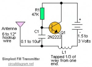
This is likely the simplest radio transmitter available. It comprises five components and can be assembled in a compact space. It is ideal for science fair projects or other science-related activities where short-range transmission is beneficial. The device operates...