
2N3904 Transistor For 200M FM Transmitter

The FM transmitter circuit typically consists of several key components: an oscillator, modulator, amplifier, and antenna. The oscillator generates a carrier frequency, which is modulated by the audio signal to transmit information. A common choice for the oscillator is a transistor-based configuration, often using a Colpitts or Hartley oscillator design, which provides stability and tunability.
The modulator section combines the audio input with the carrier frequency. This can be accomplished using a transistor or operational amplifier configured to modulate the amplitude or frequency of the carrier signal based on the input audio. The modulation depth and linearity are critical parameters that affect the quality of the transmitted signal.
The amplifier stage boosts the modulated signal to a sufficient level to drive the antenna. This stage may employ a class A or class C amplifier design, depending on the desired efficiency and linearity. Proper biasing of the amplifier transistors is essential to ensure optimal performance and prevent distortion.
The antenna, which can be a simple dipole or monopole design, is tuned to the operating frequency of the transmitter. The length and configuration of the antenna must be matched to the frequency to maximize radiation efficiency and minimize standing wave ratio (SWR).
To achieve a range of approximately 200 meters, it is crucial to ensure that all components are carefully selected and matched, including the use of appropriate capacitors and inductors in the oscillator and matching network. Additionally, the circuit layout should minimize parasitic capacitance and inductance, which can adversely affect performance.
Overall, this FM transmitter circuit provides a reliable and effective means of wireless audio transmission, suitable for various applications such as personal broadcasting, educational projects, or hobbyist experimentation.This circuit have a very stable and simple FM transmitter circuit. This transmitter can attain a range of around 200 meters if have a matching .. 🔗 External reference
Related Circuits
The mixer consists of two transistor-based preamplifiers. The first one, designated as "Mike," provides high gain and is designed to work effectively with a standard dynamic microphone. The second preamplifier can be used to control audio input from a...

This circuit represents an FM transmitter, also referred to as an FM Bug, which consists of 18 essential components for optimal functionality. The circuit begins with an electret microphone on the far left side, and the signal flows electrically...
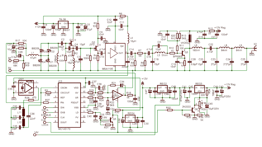
In order to simplify the transmitter design, we've used the new pll circuit from Motorola: the MC145170. This PLL includes the prescaler and a serial standard bus called SPI. We advise to use the P2 version that fixes some...

The circuit was constructed using a few components powered by a 9 V battery to sense the presence of bugs transmitting within the frequency modulation. The circuit design utilizes a 9 V battery as the primary power source, making it...

The function of this circuit is an audio amplifier capable of delivering a decent output power with a minimal number of components, with considerable efficiency. This audio amplifier circuit is designed to enhance audio signals, providing sufficient output power while...

This compact FM transmitter is designed for connection to a USB port and has a range of approximately 50 meters. It can be utilized alongside multiple mini-transmitters to create a diverse and engaging radio program. The power supply through...