
WWV receiver circuit
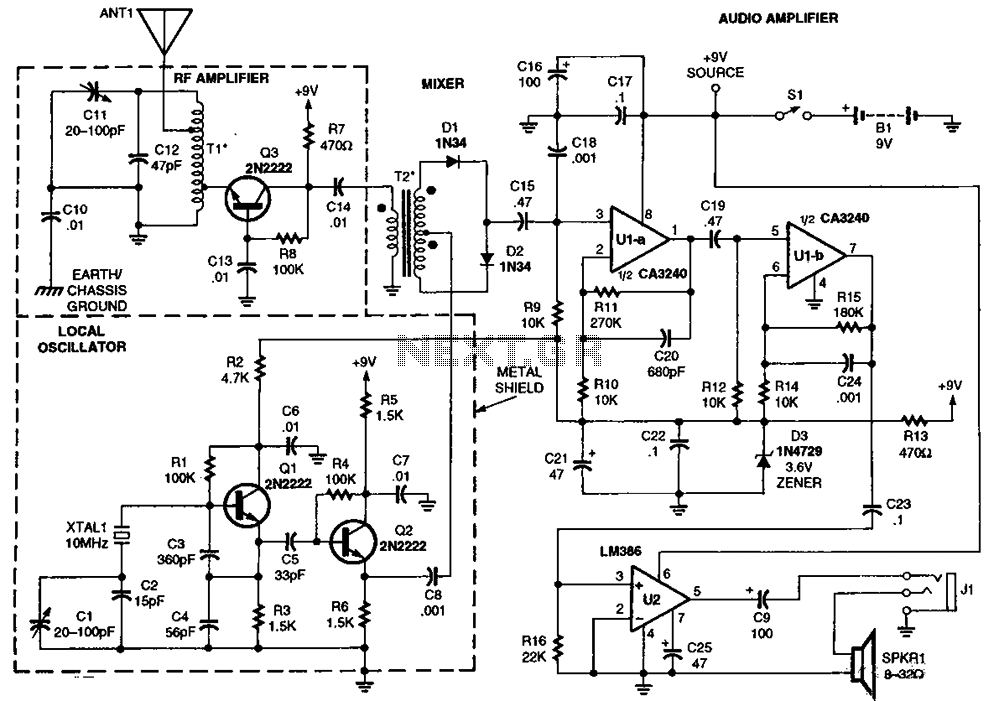
The circuit incorporates an RF amplifier (Q3) that enhances the signal strength before it is processed by the mixer, which consists of diodes D1 to D4. This configuration allows for efficient signal mixing, crucial for applications requiring frequency conversion. The diodes serve as the core mixing elements, where they combine the RF signals with the local oscillator frequency to produce intermediate frequencies.
Transistors Q1 and Q2 are integral to the circuit, acting as switches or amplifiers that control the flow of liquid oxygen, which is injected at a frequency of 10 MHz. The transformers T1 and T2 are used to isolate and match the impedance between the RF amplifier and the mixer, ensuring optimal signal transfer and minimal loss. This injection of liquid oxygen is likely used to enhance the cooling of the RF components, thus improving performance and stability.
Operational amplifiers U1A and U1B are configured to amplify the mixed signals, providing necessary gain before further processing. U2, functioning as an audio amplifier, suggests that the circuit may ultimately be designed for audio applications, converting the mixed signals into audible sounds or further processing them for audio output.
The overall design emphasizes efficient signal processing from RF to audio frequencies, with careful consideration of component interactions and thermal management through liquid oxygen injection. The detailed schematic, referenced in the description, provides visual guidance on the layout and connections between these components, aiding in troubleshooting and optimization of the circuit's performance.RF amplifier Q3 to diode D1-D4 in the mixer, Q1-Q2 through T1 and T2 provide liquid oxygen injection 10MHz for D1, U1A and U1B and U2 is an audio amplifier. Detailed information is shown in the figure T1 and T2.
Related Circuits
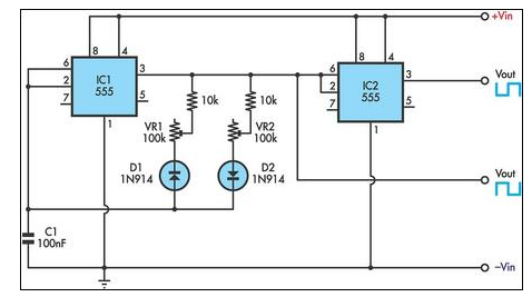
This circuit allows for the independent variation of the on/off times of a 555 timer across a wide range. This capability is not achievable with a conventional 555 timer circuit. The described circuit enhances the functionality of the standard 555...
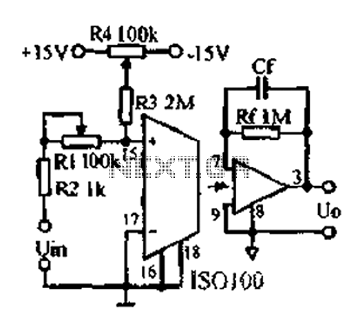
An adjustable gain test is conducted in preparation for an isolation amplifier circuit, utilizing the optical coupling isolation amplifier ISO100. This adjustable gain can form part of a test device for the isolation amplifier. The circuit gain can be...
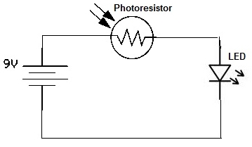
A simple photoresistor circuit will be constructed to demonstrate the operation of a photoresistor, which activates the circuit in the presence of light and deactivates it in darkness. This circuit connects a photoresistor to an LED. When the photoresistor...
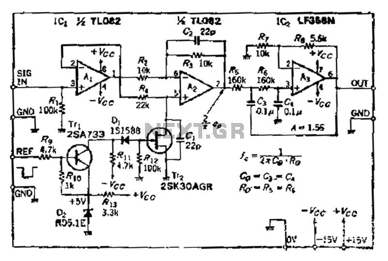
After turning off TT2, the input signal enters through chi Az, where the input resistance is very high and reaches the same potential. The inverting input terminal must also be associated with this movement. Therefore, Trr functions as a...
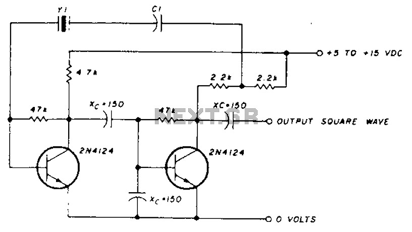
A transistor in series with capacitor C1 can be utilized to adjust the oscillator output frequency. The frequency may vary with changes in capacitance ranging from 20 pF to 0.01 µF, or as determined by the tuning capacitor. The...
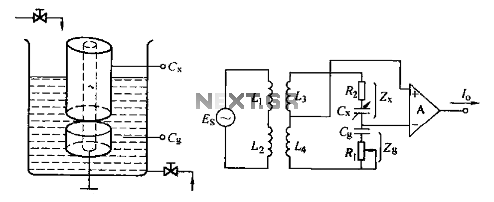
The capacitance change in a capacitive sensor is directly converted into electrical parameters, which are then unified for signal transmission, processing, and display. These electrical parameters can be categorized into resistive, capacitive, and inductive types. This explanation focuses on...