
Adjustable gain amplifier circuit diagram of a test device isolation

The described isolation amplifier circuit employs the ISO100, which is known for its high performance in providing electrical isolation while maintaining signal integrity. The adjustable gain feature allows for flexibility in applications that require varying levels of amplification. The gain adjustment is typically achieved using a variable resistor or a digital potentiometer, enabling precise control over the amplification factor.
In this configuration, the input signal, which is negative in polarity, is fed into the ISO100. The amplifier processes this signal while ensuring that any common-mode noise is rejected, thus preserving the quality of the output signal. The output of the ISO100 is also connected to a load or subsequent stage of processing, which can be powered by the same 15V supply that powers the input stage.
The gain range from 10 to 1000 allows for a wide variety of applications, from low-level signal amplification to more substantial signal conditioning tasks. This versatility makes the circuit suitable for use in various fields, including medical instrumentation, industrial monitoring, and communication systems. Proper attention must be given to the power supply decoupling and grounding to minimize interference and ensure stable operation.
Overall, the adjustable gain isolation amplifier circuit using the ISO100 is a robust solution for applications requiring high isolation and variable gain, facilitating accurate signal processing in sensitive environments.Adjustable Gain Test in preparation isolation amplifier circuit as shown below, the use of optical coupling isolation amplifier ISO100, adjustable gain can be composed tone tes t device isolation amplifier. The circuit gain can be adjusted in the range from 10 to 1000. Enter the code signal will be negative. ISO100 input, output, respectively, by two 15V supply.
Related Circuits
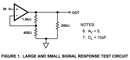
Here is a circuit diagram for a signal response test circuit from the specification sheet for a HA-5195 operational amplifier. It appears to be a non-inverting amplifier circuit with a gain of 5, along with a 200-ohm resistor connecting...
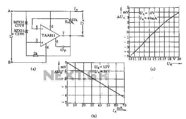
The regulator circuit adjusts the output voltage based on the potentiometer Rp and exhibits linear regulation characteristics. The output voltage Ua varies with the load current Ia, ranging from 0 to 70 mA, as illustrated in Figure (C) for...
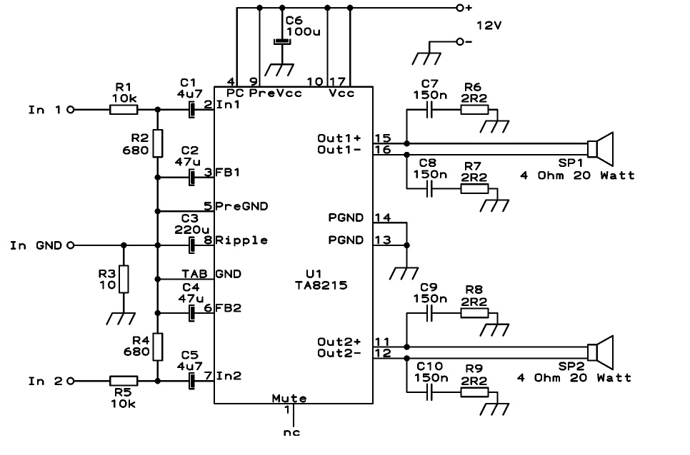
This circuit is designed as a stereo BTL (Bridge-Tied Load) 15W audio power amplifier using the TA8215 integrated circuit developed by Toshiba. Two TA8215 ICs are utilized in this configuration to achieve four output channels, with each IC providing...
The circuit diagram is designed for precise control of DC motors. It converts DC voltage into a series of pulses, where the duration of each pulse... The circuit utilizes a pulse-width modulation (PWM) technique to regulate the speed and torque...
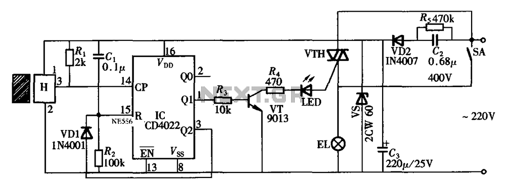
The circuit illustrated in the figure depicts an automatic bathroom light switch system. When the door is opened, the light is activated, illuminating the space. Conversely, when the door is opened again, the light turns off. The circuit comprises...
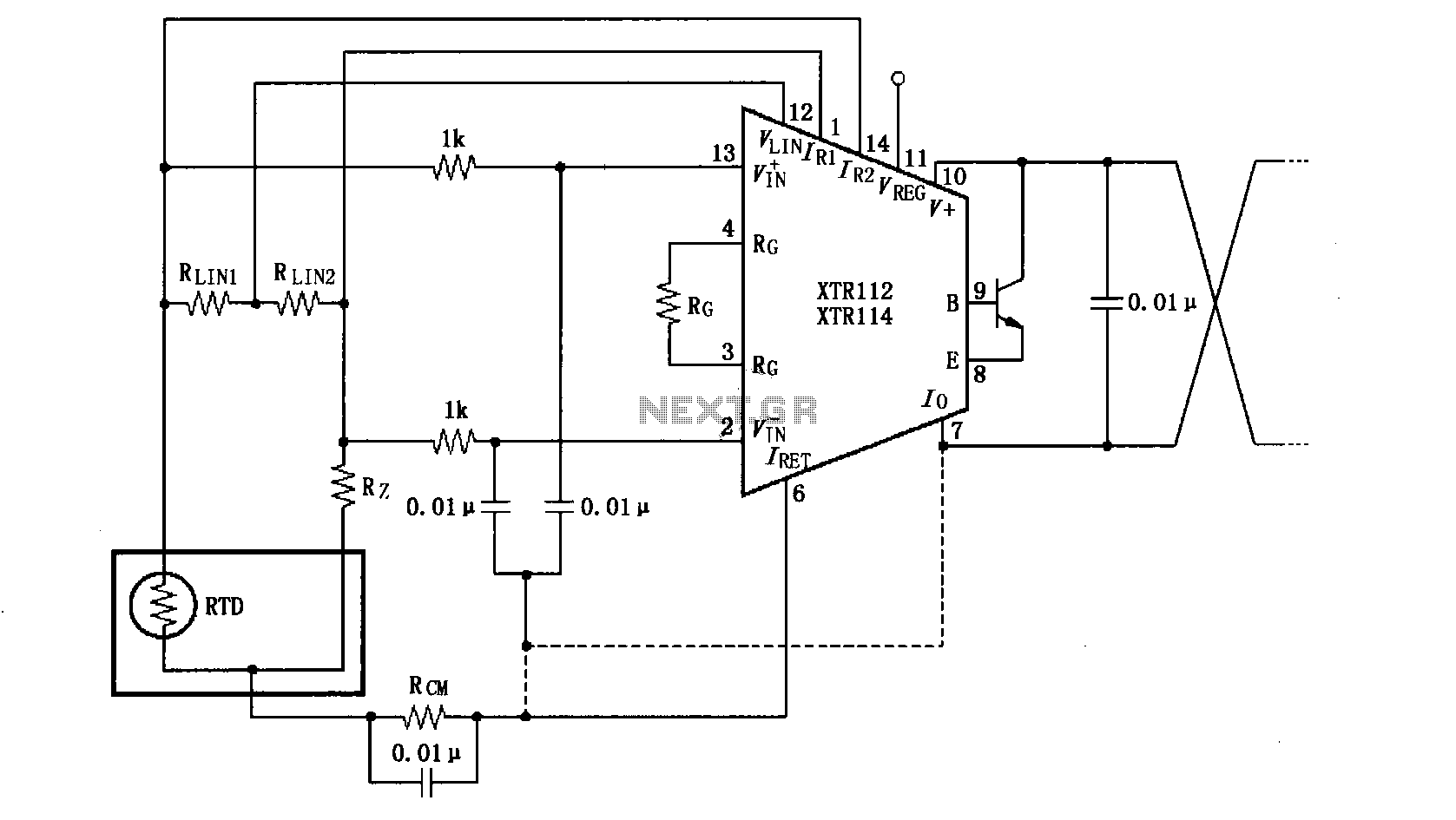
The length of the transmission wire in a current loop circuit can introduce radio frequency (RF) interference. This RF energy may lead to input errors in sensitive devices such as the XT112/114, causing instability in loop current or input...