
usb sound card with pcm 2702

The PCM2702 integrated circuit serves as a versatile solution for USB audio applications. It simplifies the design of USB sound cards by integrating essential functionalities into a single chip. The digital-to-analog conversion is performed with high fidelity, ensuring that audio playback is clear and accurate. The compliance with USB 1.1 standards allows for broad compatibility with various devices without the need for additional drivers, enhancing user convenience.
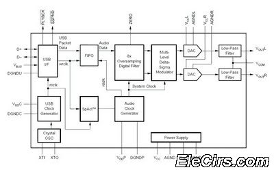
The circuit design incorporates the PCM2702’s D+ and D- pins, which are critical for USB data communication. The full-speed data transfer capability ensures that audio signals are transmitted efficiently, maintaining the integrity of the sound quality. The output pins, VOUTL and VOUTR, provide stereo audio signals that can be connected directly to speakers or an audio amplifier.
The inclusion of a 12 MHz crystal oscillator is vital for the proper timing and functioning of the PCM2702. This clock signal is necessary for synchronizing the digital processing within the IC. The power supply connections to the VBUS and DGND pins are crucial for the operation of the device, as they provide the necessary voltage levels for the internal circuitry.
Additionally, the use of low-dropout voltage regulators to derive the operating voltages from the USB port enables efficient power management. This feature is particularly beneficial in portable applications where battery life is a concern. The design can be further enhanced by adding filtering capacitors to the power supply lines to minimize noise and improve audio performance.
Overall, the PCM2702 represents a robust and efficient solution for creating USB sound cards, providing a complete audio processing solution in a compact package. The integration of multiple functions into a single IC streamlines the design process, making it accessible for engineers and hobbyists alike.Designing and building a USB sound card longer a head ache got the PCM 2702 integrated circuit from Texas Instruments. The PCM2702 is an integrated bit digital to analog converter that has digital to analog output channels.
The integrated interface controller of PCM2702 is compliant to the USB. 0 standards. The IC handle sampling rates of KHz, 44. 1 KHz and KHz. The IC of helpful like on-chip clock generator, digital attenuator, play back flag, suspend flag, zero flag, mute etc. is that this circuit is plug & play and doesn`t any driver software for Windows XP and Windows Vista operating systems.
The circuit gets and audio from the USB through the D+ and D- pins of the PCM2702 all transferring is at full speed. The decoded audio signals at the VOUTL and VOUTR pins of the IC. The 12MHz crystal is connected between the XT0 and XT1 pins of the IC. The VBUS (USB bus power) pin and DGND (digital ground) pins of the IC are connected to the +5V and ground pins of the USB respectively.
The circuit +5V DC and +3. 3V DC for operation and voltages derived from the USB port using LDO (low drop out) voltage regulators (not shown in circuit). 🔗 External reference
Related Circuits

The device utilizes the USB boot HID keyboard protocol. When connected, it can detect changes in the keyboard LED states (caps lock, num lock, scroll lock), which the firmware uses to initiate new password generation (indicated by four LED...
The USB sound card circuit utilizes the PCM2702 integrated circuit (IC) to create a fully functional USB sound card. The design is straightforward, allowing for the easy implementation of audio processing capabilities. The PCM2702 is a versatile USB audio controller...
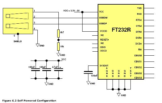
One issue this creates is that the USB port previously used for communication with HyperTerminal is no longer available. An alternative solution is required, which led to the selection of the FT232RL chip. This choice was made primarily due...
The idea to produce a standard TV PAL signal using a SVGA graphics card was born a few years ago, where cheap graphics cards with TV output were still not available. To achieve a CCIR conform TV signal with...
This is a metronome circuit that produces a mechanical sound characteristic. A metronome with a mechanical sound character enhances the enjoyment of musical practice and performance. The metronome circuit is designed to generate a rhythmic sound that aids musicians in...
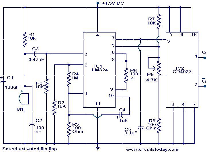
The following circuit illustrates a Sound Operated Flip Flop. This circuit is based on the LM324 integrated circuit. It features a condenser microphone used for sound detection. The Sound Operated Flip Flop circuit utilizes the LM324 operational amplifier, which consists...