
Rms-to-dc converter

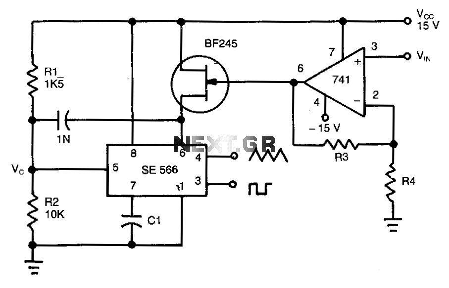
The described circuit functions as a straightforward RMS-to-DC converter, utilizing a demodulator to process the AC input signal. At Pin 4, the AC input is fed into the demodulator, which is designed to rectify this signal. The rectification process is full-wave, meaning that both halves of the AC waveform are utilized, resulting in a more efficient conversion to DC.
Pin 5 serves as the output of the demodulator, where the rectified signal can be observed. This signal contains a DC component that is directly proportional to the RMS value of the AC input at Pin 4. The linear relationship between the DC output at Pin 1 and the RMS input at Pin 4 ensures that the circuit can provide accurate voltage readings, making it suitable for applications requiring precise measurements.
The circuit's simplicity is underscored by its low component count, which not only reduces costs but also enhances reliability. The variable capacitor (CT) plays a crucial role in ensuring that the demodulator operates correctly. By adjusting CT, the sync signal is aligned with the AC input, optimizing the performance of the demodulator. This adjustment is critical for achieving accurate phase alignment, which ensures that the rectification process occurs effectively.
The output at Pin 1 can be connected to an AC voltmeter or other measuring devices to display the converted DC value. The design's straightforward nature allows for easy assembly and troubleshooting, making it an attractive option for engineers and hobbyists alike. Overall, the circuit provides a reliable method for converting AC signals to a DC representation, suitable for various electronic measurement applications.The DC output at Pin 1 vanes linearly with the RMS input at Pin 4. 2 CT is tweaked until the svnc signal is in phase with the AC signal. An ac voltmeter may be easily constructed. Simplicity of the circuit and low component count make it particularly attractive. The demodulator output is a full-wave rectified signal from the ac input at Pin 4. The dc component on the rectified signal at Pin 5 varies linearity with the rms input at Pin 4 and thus provides an accurate rms-to-dc conversion at the output of the filter (Pin 1). CT is a variable capacitor that is tweaked until the oscillator signal to the sync input of the demodulator is in phase with the ac signal at Pin 4.
Related Circuits
Normally analogue-to-digital converter (ADC) needs interfacing through a microprocessor to convert analogue data into digital format. This requires hardware and necessary software, resulting in increased complexity and hence the total cost. The circuit of A-to-D converter shown here is...
This circuit operates based on the frequency variation of the function generator in relation to the input voltage (ViN). The frequency is influenced by the capacitance and resistor connected to pin 6, with the resistor being substituted by a...
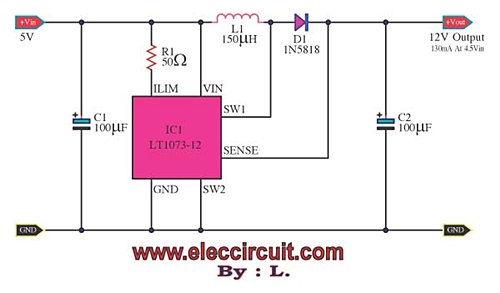
Suppose there is a need to utilize a 5V DC power supply capable of delivering up to 100mA, but only a single AA 1.5V battery is available. To achieve this, a DC to DC converter must be employed. To convert...
This inverter circuit can provide up to 800mA of 12V power from a 6V supply. For example, you could run 12V car accessories in a 6V (British?) car. The circuit is simple, about 75% efficient and quite useful. By...

This design circuit is for converting voltage to frequency. Typically, frequency meters are used in speed sensors, tachometers, and for measuring recurring signals. The frequency to voltage converter (FVC) can transform voltage into either a digital or analog tachometer....
The VGA-to-Scope converter schematic has been simplified by removing op-amp buffers and inverters. A 1 Megohm potentiometer can be used instead of a continuous current supply to charge the capacitor from a 5V source. Proper placement of the potentiometer...