
Dark Seeker - TV-to-Scope Converter

The VGA-to-Scope converter circuit facilitates the conversion of VGA signals into a format suitable for oscilloscope analysis. The simplification of the circuit design, particularly the removal of op-amp buffers and inverters, enhances the reliability and reduces the complexity of the overall system. The use of a 1 Megohm potentiometer connected to a 5V supply serves as an adjustable charging mechanism for the capacitor, enabling fine-tuning of the charge rate to optimize performance.
In this configuration, the capacitor plays a crucial role in storing the voltage level of the VGA signal for analysis. By adjusting the potentiometer, the user can control the time constant of the charging circuit, which directly affects the signal representation on the oscilloscope. The trigger signal from the 555 timer is essential for synchronizing the discharge of the capacitor, ensuring that the oscilloscope captures the correct signal waveform at the appropriate time.
This design provides a more user-friendly approach to interfacing VGA signals with oscilloscopes, allowing for easier troubleshooting and analysis of video signals. The elimination of unnecessary components not only simplifies the circuit but also reduces potential points of failure, thus enhancing overall reliability.If you refer to the above schematic, you`ll notice that the VGA-to-Scope converter has been simplified, while op-amp buffers and inverters were simply eliminated. The continuous current supply to charge up the capacitor can be replaced by a 1Meg pot from 5V to charge up the capacitor constantly.
If you placing the pot at the right position, the ca pacitor will be charge up, and the trigger signal stopped the 555 to discharge the capacitor. We aim to transmit more information by carrying articles. Please send us an E-mail to wanghuali@hqew. net within 15 days if we are involved in the problems of article content, copyright or other problems. We will delete it soon. 🔗 External reference
Related Circuits
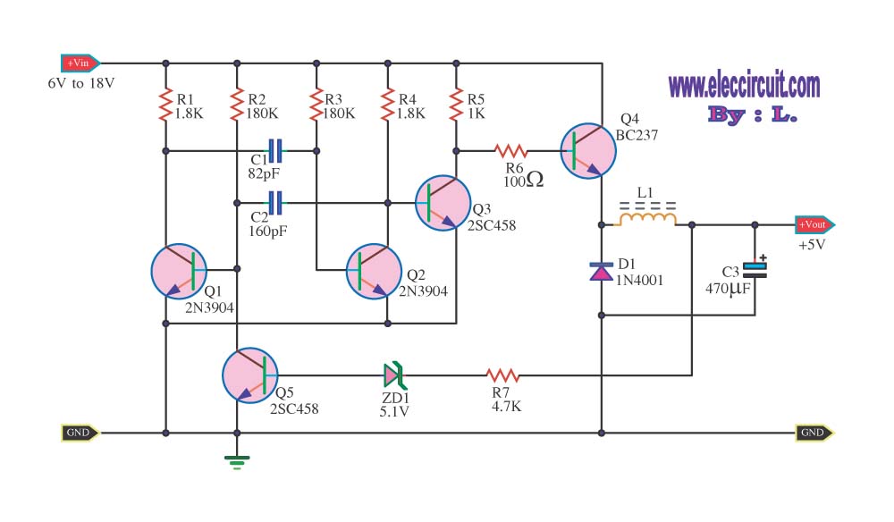
The circuit reduces voltage size or functions as a step-down voltage converter circuit, which is a DC regulated circuit model utilizing a switching converter. This design generates a specific voltage output. The step-down voltage converter, also known as a buck...
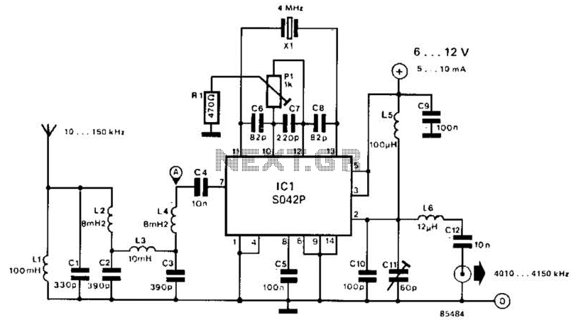
This converter shifts frequencies from 10 kHz to 150 kHz up to 4.01 to 4.15 MHz, suitable for use with a shortwave receiver for very low frequency (VLF) reception. A 4 MHz local oscillator frequency is utilized, and the...
The AD7781 is a complete low-power front-end solution for bridge sensor products, including weigh scales, strain gauges, and pressure sensors. It contains a precision low-power 20-bit sigma-delta ADC, an on-chip low-noise programmable gain amplifier (PGA), and an on-chip oscillator....
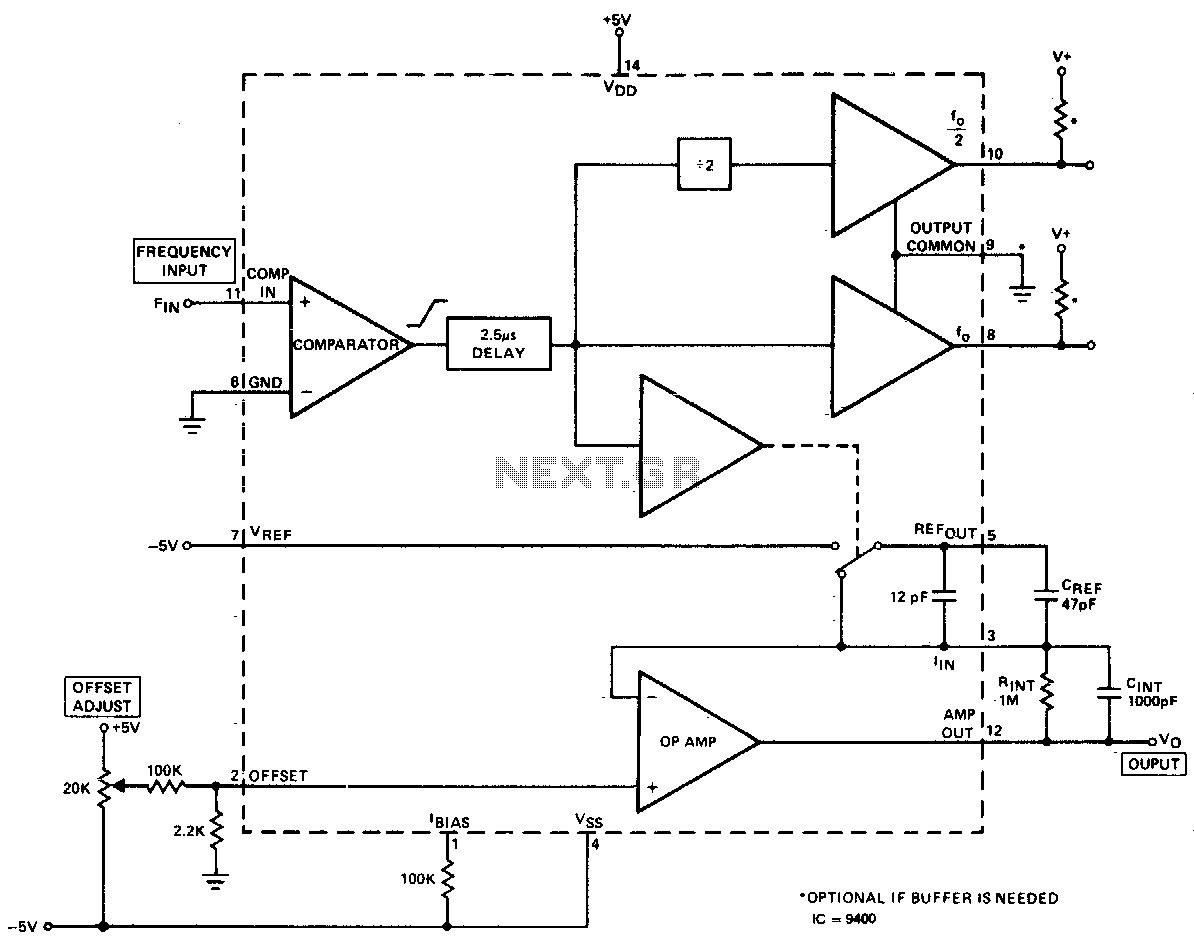
The converter produces an output voltage that is linearly proportional to the input frequency waveform. Each zero crossing at the comparator's input results in a specific amount of charge being dispensed into the op-amp's summing junction. This charge subsequently...
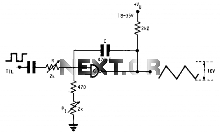
This fixed-frequency triangular waveform generator, driven by a TTL square wave, produces triangular waveforms with a peak-to-peak voltage of typically 16 V at frequencies reaching several MHz. The design utilizes a single AND open collector gate or an open...
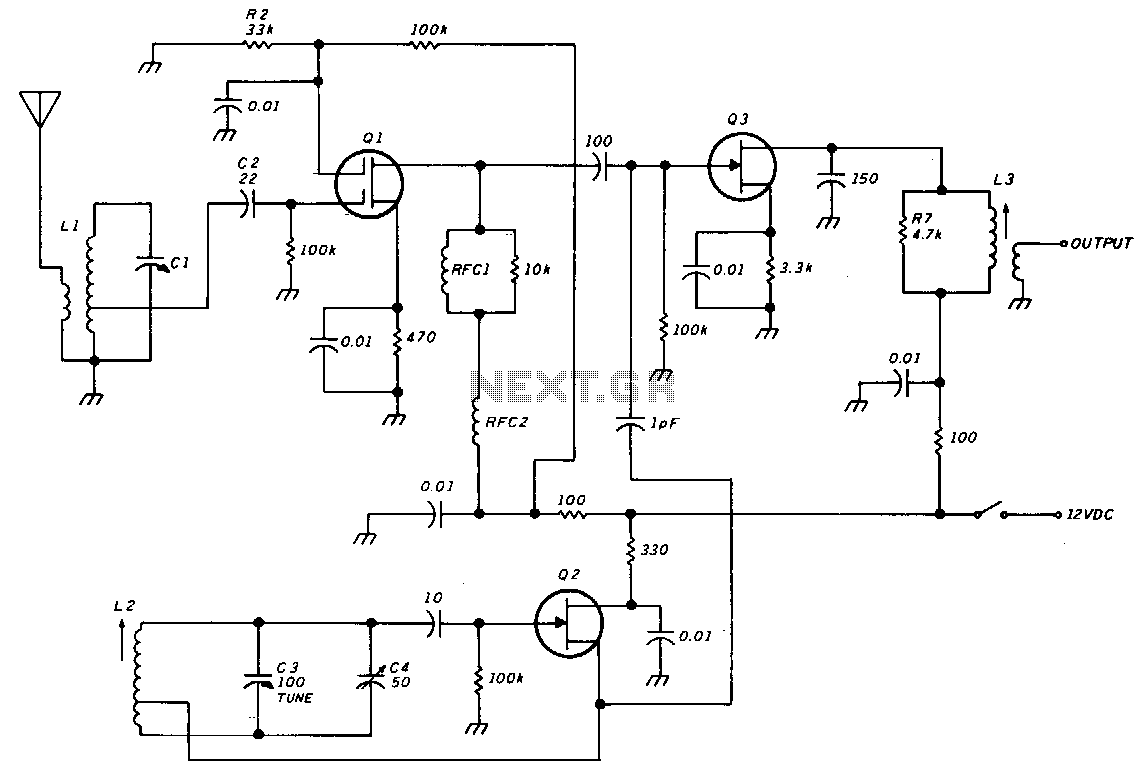
The unit consists of an RF amplifier Q1, a local oscillator Q2, and a mixer Q3. The two frequency bands are covered without a band switch by utilizing an intermediate frequency (IF) of 3.5 MHz. The oscillator operates within...