
Analog to Digital Converter with ADC0808

The ADC 0808 is a versatile 8-bit analogue-to-digital converter designed to facilitate the conversion of analogue signals to digital representation without the necessity of a microprocessor. It employs the successive approximation method, which enhances the efficiency and speed of conversion. The device features eight analogue input channels, allowing for the selection of one channel via address lines A, B, and C. In the described configuration, the IN0 channel is selected by grounding the address lines, simplifying the connection process.
Control signals are critical for the operation of the ADC. In this configuration, the signals EOC, SC, ALE, and OE are managed in a way that eliminates the need for a microprocessor. The ALE and OE signals are tied to the positive supply voltage (Vcc), ensuring they remain active-high. The SC signal, being active-low, is triggered by a falling edge, initiating the conversion process. The EOC signal indicates the completion of the conversion, transitioning to a high state, which is then used to trigger the next conversion cycle through its connection to the SC input.
The ADC 0808 requires a clock signal of approximately 550 kHz, which can be generated using an astable multivibrator circuit constructed with 7404 inverter gates. This clock signal is essential for the timing of the conversion process. The digital output of the ADC is presented through eight data lines (D0-D7), which can be visualized using a series of LEDs. Each LED corresponds to a data line, allowing for immediate visual feedback of the digital output based on the analogue input.
To ensure accurate conversion, the input voltage must be scaled appropriately, remaining below the specified maximum reference voltage of +5V. The conversion process yields an 8-bit digital output, which can be calculated based on the relationship between the analogue input voltage and the digital representation. This setup provides a continuous output, making it suitable for applications requiring real-time monitoring of analogue signals. Normally analogue-to-digital con-verter (ADC) needs interfacing through a microprocessor to convert analogue data into digital format. This requires hardware and necessary software, resulting in increased complexity and hence the total cost.
The circuit of A-to-D converter shown here is configured around ADC 0808, avoiding the use of a microprocessor. The ADC 0808 is an 8-bit A-to-D converter, having data lines D0-D7. It works on the principle of successive approximation. It has a total of eight analogue input channels, out of which any one can be selected using address lines A, B and C.
Here, in this case, input channel IN0 is selected by grounding A, B and C address lines. Usually the control signals EOC (end of conversion), SC (start conversion), ALE (address latch enable) and OE (output enable) are interfaced by means of a microprocessor. However, the circuit shown here is built to operate in its continuous mode without using any microprocessor.
Therefore the input control signals ALE and OE, being active-high, are tied to Vcc (+5 volts). The input control signal SC, being active-low, initiates start of conversion at falling edge of the pulse, whereas the output signal EOC becomes high after completion of digitisation. This EOC output is coupled to SC input, where falling edge of EOC output acts as SC input to direct the ADC to start the conversion.
As the conversion starts, EOC signal goes high. At next clock pulse EOC output again goes low, and hence SC is enabled to start the next conversion. Thus, it provides continuous 8-bit digital output corresponding to instantaneous value of analogue input. The maximum level of analogue input voltage should be appropriately scaled down below positive reference (+5V) level.
The ADC 0808 IC requires clock signal of typically 550 kHz, which can be easily derived from an astable multivibrator constructed using 7404 inverter gates. In order to visualise the digital output, the row of eight LEDs (LED1 through LED8) have been used, wherein each LED is connected to respective data lines D0 through D7.
Since ADC works in the continuous mode, it displays digital output as soon as analogue input is applied. The decimal equivalent digital output value D for a given analogue input voltage Vin can be calculated from the relationship.
🔗 External reference
Related Circuits
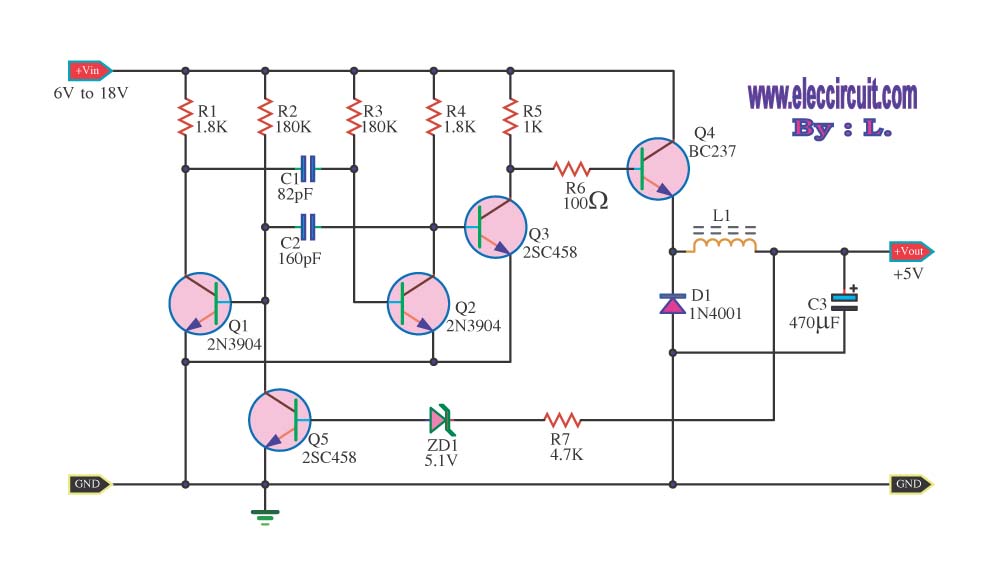
The circuit reduces voltage size or functions as a step-down voltage converter circuit, specifically a DC regulated circuit model using a switching converter. It generates the desired voltage output. The step-down voltage converter circuit, also known as a buck converter,...
Basically, this is a frequency-current converter. It is used as a frequency meter. Calibrating it can be used as a tachometer. Please be aware this is an experimental project; it wasn't connected to any vehicle, but it should work...
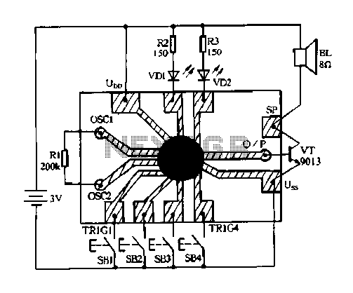
Constantly changing light and sound analog controller circuit 04 The circuit designated as the "Constantly Changing Light and Sound Analog Controller Circuit 04" is designed to modulate both light and sound outputs in a dynamic manner. This type of...
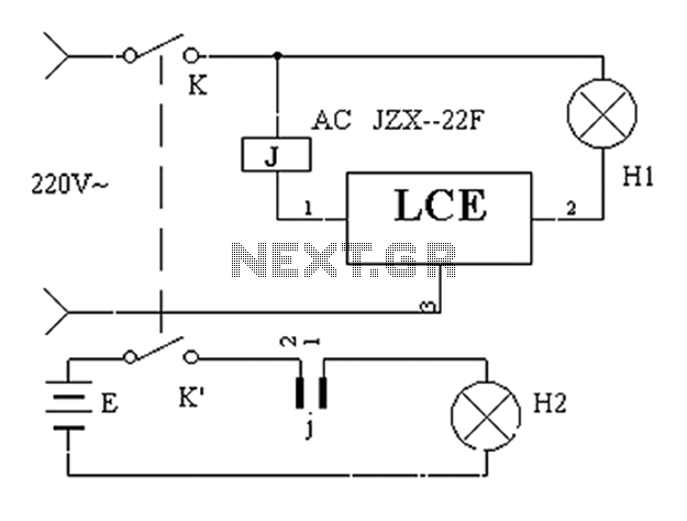
The application circuit operates the device as illustrated below, allowing for intermittent lighting in specific situations (e.g., during surgery). It utilizes an LCE module for blackout emergency lighting, which activates automatically after a power failure, ensuring uninterrupted illumination. In...
This type of converter is used to convert analog voltage to its corresponding digital output. The function of the analog-to-digital converter is exactly opposite to that of a digital-to-analog converter. Like a digital-to-analog converter, an analog-to-digital converter is also...
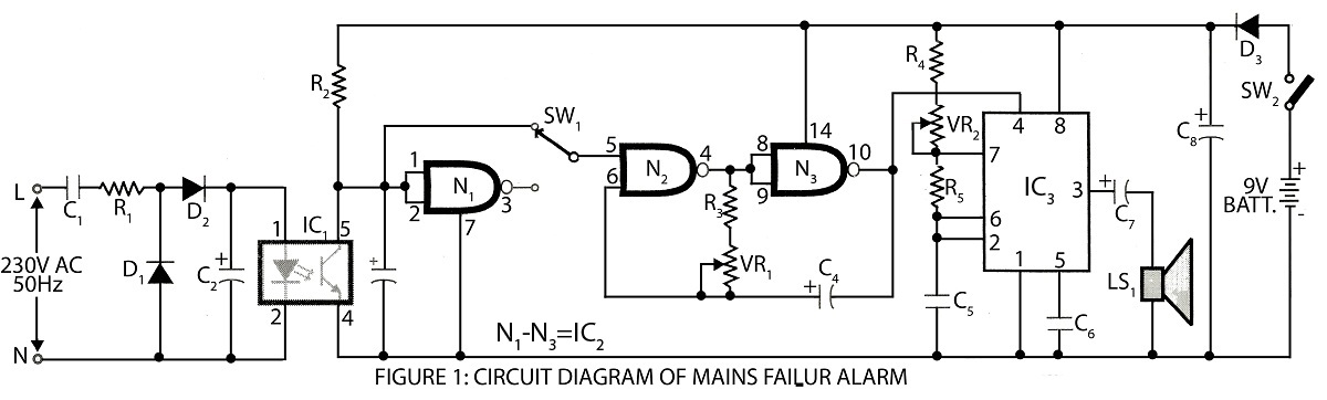
A digital mains failure and resumption alarm circuit utilizes an optocoupler to generate an audible sound. This circuit diagram includes a description of various alarm circuits for digital mains failure. The digital mains failure and resumption alarm circuit is designed...