
Robot Autonomous Sensor Platform

The autonomous robot operates based on a microcontroller architecture centered around the PICAXE processor, which is well-suited for educational and experimental robotic applications. The robot is equipped with an array of sensors that facilitate its navigational and operational capabilities. These sensors may include ultrasonic distance sensors for obstacle detection, infrared sensors for line following, and magnetic sensors for detecting the presence of a magnet.
The design incorporates a power supply circuit that ensures the PICAXE processor and sensors receive stable voltage levels, typically from a battery pack. The robot's movement is controlled by a motor driver circuit that interfaces with the PICAXE, allowing for precise control of the motors that drive its wheels. The motor driver can be an H-bridge configuration, enabling the robot to move forward, reverse, and turn.
The software programming for the PICAXE processor is crucial, as it dictates the robot's behavior and decision-making processes. The code will handle sensor input, process the data, and control the motors based on predefined algorithms. For instance, when the ultrasonic sensor detects an obstacle within a specified range, the robot can be programmed to stop, reverse, or change direction.
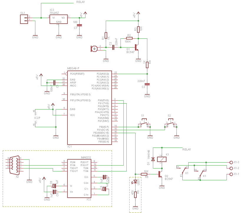
To enhance its functionality, the robot may include additional features such as LED indicators for status signaling, a buzzer for auditory feedback, and a communication module for remote control or telemetry. The overall schematic of the robot would illustrate the interconnections between the PICAXE processor, sensors, motor drivers, and other components, providing a clear representation of the system's architecture.
In summary, this autonomous robot serves as a practical platform for exploring sensor interfacing and microcontroller programming, showcasing the integration of hardware and software in robotic applications.This is my first autonomous robot. I built it to explore the interfacing of various sensors to a PICAXE processor. His mission is to search for a magn.. 🔗 External reference
Related Circuits
The strategy focused on efficiently navigating complex terrain with superior speed. The objective was to score in the lowest scoring goal by acting quickly to limit the opposing team's points. The mechanical and electrical designs prioritized speed, resulting in...
The objective of this project is to utilize an inexpensive PIR sensor to detect human movement. A PIC18F25K20 microcontroller is employed to monitor changes in the sensor's state and emit sound through a speaker or piezo buzzer. The microcontroller...
This week's plan is to build a device that warns of the potential for a knockdown, which is the process by which an over-canvassed ship is laid over on her beam-ends. The risk of sinking is high during this...

The following circuit illustrates the LM2940CT sensor connection circuit diagram. Features include internal power dissipation and a storage temperature range. The LM2940CT is a low dropout linear voltage regulator designed to provide a stable output voltage with a maximum dropout...
The final project involves cycling rollers that require a method to sense the rotational speed of one of the rollers. Speed sensors on bicycles typically function by detecting a magnet attached to a spoke on one of the wheels...

The Proximity Sensor circuit is illustrated below. Three red boxes indicate the additions to the circuit previously constructed in Part 2: Motor Control. The new components included in the schematic are the GP2Y0A21YK IR Sensor, a headphone speaker, and...