
IR remote control dimmer light circuit diagram

The infrared emission circuit utilizes the NE555 timer IC configured in astable mode to produce a continuous square wave output at a frequency of 40 kHz. This frequency is optimal for infrared communication, allowing the emitted pulses to be modulated for efficient transmission. The NE555 output drives the SE303 infrared emitter, which converts the electrical pulses into infrared light.
The SE303 acts as an infrared LED driver, amplifying the pulse signal from the NE555. The transistor VT is employed to further amplify the current, ensuring that the infrared LED emits sufficient intensity for effective communication over a distance. The choice of VT is critical, as it must be capable of handling the required current without overheating or entering saturation.
On the receiving end, the KA2184 serves as the infrared receiver and dimming controller. It detects the modulated infrared signal and demodulates it to retrieve the original pulse signal. This IC is designed to operate efficiently in low-light conditions, making it suitable for applications such as remote controls and dimming systems.
The LS7232 integrated circuit is utilized in conjunction with the KA2184 for advanced dimming capabilities. It provides additional features such as adjustable brightness levels, allowing users to control the intensity of the output light based on the received infrared signals. The integration of these components results in a robust system capable of precise control over infrared lighting applications, enhancing both functionality and user experience.
Overall, this circuit represents a comprehensive solution for infrared emission and reception, integrating multiple components to achieve effective communication and control in electronic lighting systems.Is infrared emission circuit diagram. NE555 circuit generates a 40kHz pulse which is sent by the infrared emission control SE303 after beingamplified by VT. (b) is remote receiver and infrared dimming circuit composed of the KA2184. LS7232 is an integrated dimming circuit. 🔗 External reference
Related Circuits
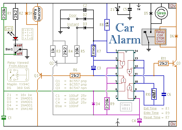
This circuit is designed to secure a vehicle at a low cost if constructed independently, making it more affordable than purchasing a commercial car alarm system. The alarm is activated by opening switch Sw1, which can be any small...
This simple FM radio receiver circuit utilizes the TDA7000 integrated circuit (IC), which incorporates nearly all the necessary functions to construct an FM receiver, requiring only a few external capacitors and a tuning circuit. The design employs a straightforward...
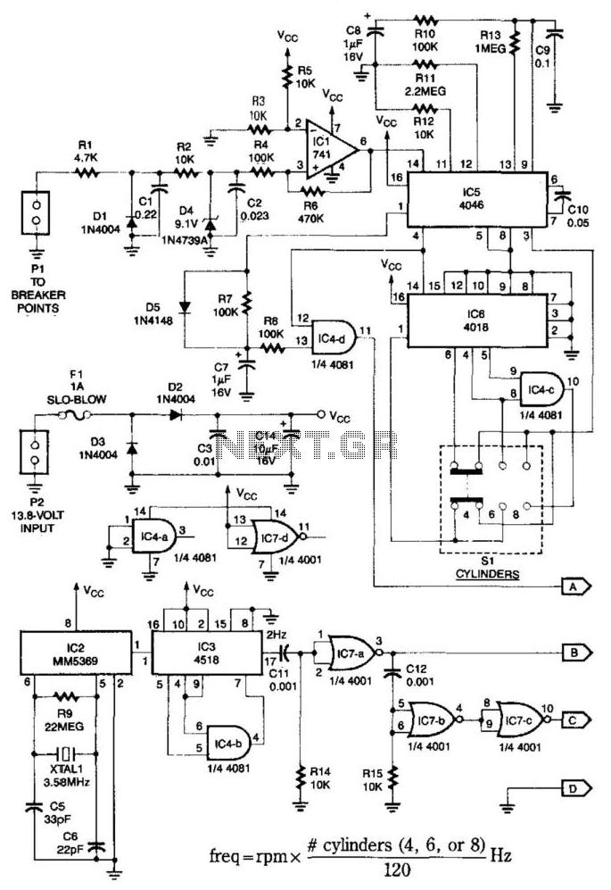
This system is compatible with 4-, 6-, or 8-cylinder automobiles. The timebase generated by IC5 functions as an oscillator that drives counter IC6, which divides the frequency by 6, 4, or 3 for 4-, 6-, or 8-cylinder engines, respectively....
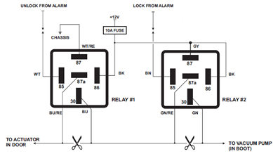
The circuit diagram displayed below illustrates a single-wire vacuum control system for pneumatic locking, commonly utilized in vehicles from Jaguar, Audi, and Mercedes. The circuit operates by managing the vacuum pressure required to engage or disengage the pneumatic locking mechanism....
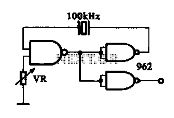
A DTL integrated circuit comprises a crystal oscillator, which is represented by the integrated circuits. The oscillation frequency ranges from 100 kHz to 1 MHz. Additionally, it includes a gate circuit that supplies a signal for the DTL oscillator...
This circuit functions with inaudible (ultrasonic) sound. Sound of frequency up to 20 kHz is audible to human beings. The sound of frequency above 20 kHz is called ultrasonic sound. The circuit described generates (transmits) ultrasonic sound of frequency...