
robotic voice generator

The ISD2500 series is designed for applications requiring high-quality audio playback and recording in a compact form factor. The microphone preamp with AGC enhances audio input quality by adjusting the gain to accommodate varying sound levels, ensuring clear recordings from inexpensive microphones. The output amplifier is capable of delivering sufficient power to drive small speakers, making it suitable for portable devices.
The integrated memory within the ISD2500 allows for the storage of voice messages, which can be recorded and played back multiple times. The oscillator generates the necessary clock signals for the chip's operation, while the ADC and DAC facilitate the conversion between analog audio signals and their digital representations, enabling efficient processing and playback of recorded audio.
In summary, the schematic diagram for the voice generator scheme using the ISD2500 series presents a complete solution for voice recording and playback, integrating essential components that work harmoniously to deliver high-quality audio performance in various applications.Voice generator scheme schematic diagram. The family of chip-coders ISD2500 firm Winbond contains almost everything you need to record and play back voice messages. As chips have mic preamps with AGC, working with the cheapest electret microphones, the output amplifier that runs on the speaker, memory, oscillator, ADC and DAC.
🔗 External reference
Related Circuits
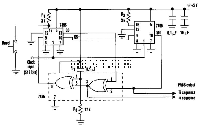
In this circuit, an additional exclusive-OR gate is connected after the modulo-2 feedback, with CI and R2 applying the supply turn-on ramp into the feedback loop. This provides sufficient transient signal so that the PRBS generator can self-start during...
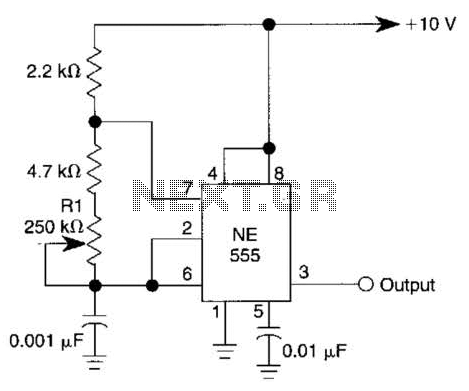
Excellent clock generator to drive 4017 type cmos circuits. R1 = 10K to 10M, C1 = 100pF to 47uF. Fo is ±1Kz when R1=100K and C1=10nF. Input voltage can be from 5 to 15V. The described clock generator circuit is...
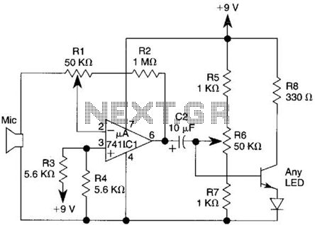
This transmitter utilizes a 741 operational amplifier as a high-gain audio amplifier, which is activated by a microphone. The output of the 741 is connected to Q1, functioning as the driver for an LED. Potentiometer R1 serves as the...
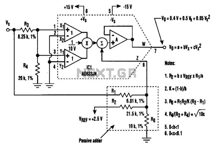
A circuit utilizing a single analog multiplier and five precision resistors can produce an output voltage (Ko) that represents a second-order polynomial. This circuit implements the quadratic function. The input terminals of IC1 are configured to create a positive...

This model features a pleasant female voice activated by a button press, and includes an alarm function that can wake users up with a rooster sound at a designated time. It also announces the time every hour, which some...
This simple square-wave generator produces a variable frequency output ranging from 2800 Hz to 80 kHz, as indicated by the specified values. The frequency can be adjusted using potentiometer R1. The square-wave generator circuit typically employs a combination of resistors,...