
Pseudo-Random Bit Sequence Generator Circuit

The circuit design incorporates an exclusive-OR gate positioned after a modulo-2 feedback mechanism, which plays a crucial role in the operation of a Pseudo-Random Binary Sequence (PRBS) generator. The configuration utilizes components CI and R2 to introduce a supply turn-on ramp into the feedback loop, effectively generating a transient signal. This transient signal is essential for enabling the PRBS generator to initiate its operation autonomously upon power-up, ensuring reliable performance.
The shift register in this design has a length of 10, with feedback connections established at stages 3 and 10. This arrangement allows for the generation of both true and inverted maximal length sequence outputs, which are fundamental for various digital communication applications. The direct application of input to the feedback loop is a significant aspect of this design, as it enhances the reliability of the circuit. Unlike traditional methods that utilize an RC configuration for resetting the shift register, which can lead to unpredictable initial states, the current approach ensures a more deterministic behavior during startup.
This circuit is particularly advantageous in scenarios where consistent and repeatable operation of the PRBS generator is required. The careful selection of feedback stages and the implementation of the exclusive-OR gate contribute to the overall stability and performance of the system, making it suitable for high-speed digital applications. The design emphasizes the importance of transient signals in circuit initialization and the benefits of direct feedback mechanisms in enhancing operational reliability. In this circuit, an additional exclusive-OR gate is connected after the modulo-2 feedback, with CI and R2 applying the supply turn-on ramp into the feedback loop. This provides sufficient transient signal so that the PRBS generator can self-start a power-up. A shift-register length of 10 is shown with feedback at stages 3 and 10, providing true and inverted maximal length sequence outputs.
This technique applies an input directly to the feedback loop. Therefore, it`s considered more reliable than applying an RC configuration to the shift-register reset input to create a random turn-on state.
Related Circuits
Connect a 12-volt, 20-watt lamp and a 12-volt battery to the circuit, ensuring correct battery polarity. Momentarily pressing and releasing the button will turn the lamp on. Repeatedly pressing the button will cycle through different power levels. Pressing and...
A basic circuit of the 89C2051 shown here can be made easily using point-to-point soldering with a universal PCB. Use an ordinary 20-pin socket, do not use a circle-pin socket. D1 is a small dot LED. U2 can be...
The car's small lamp and headlight can drain the battery if they are not turned off, leading to engine starting issues. A simple circuit, developed around 1980, can prevent this problem. It includes a series circuit with a diode...

The soft start circuit refers to a power circuit where the output voltage gradually increases to a specified value, thereby protecting the load circuit from unwanted voltage surges. It can output a voltage of 24V and a current of...
This type of design can produce a very high amperage current for a fraction of a second that can be used to do some useful work if properly harnessed. A point to remember is that Paul Baumann built his...
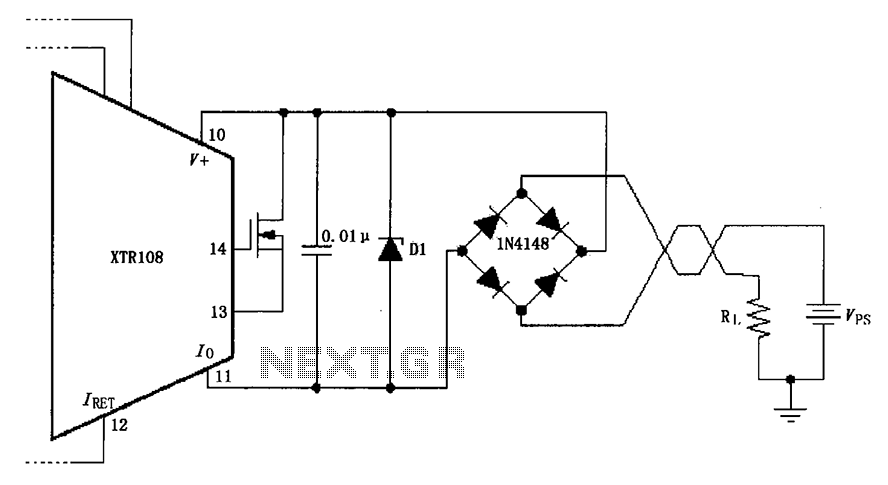
The circuit utilizes a Zener diode (D1) for overvoltage protection and a diode rectifier bridge for reverse voltage protection. The 1.4V drop across the diodes will result in a maximum voltage loss, meaning that the supply voltage (VPS) must...