
Robotics IR Navigation Sensor

The Robotics IR Navigation Sensor Circuit utilizes an inverter IC, specifically the 74HC04, to process signals from the infrared (IR) sensors. This circuit is typically employed in robotic applications for navigation and obstacle detection. The 74HC04 contains six independent inverters, which can be used to amplify and condition the signals received from the IR sensors.
The IR sensors in this configuration emit infrared light and detect the reflection from nearby objects. When an object is detected, the reflected IR light is received by the sensor, which generates a corresponding electrical signal. The output of the IR sensor is then fed into one of the inverters on the 74HC04 chip. The inverter converts the signal, effectively changing its logic state, which can be used to trigger further actions in the robotic system, such as steering or stopping.
In addition to the 74HC04, the circuit may include passive components such as resistors and capacitors to filter noise and stabilize the operation of the sensors. The design must account for the operational conditions, ensuring that the IR sensors function effectively under various lighting conditions, including direct sunlight. This requires careful selection of the sensor type and possibly the implementation of additional circuitry to enhance performance in bright environments.
Overall, this circuit design is fundamental for creating autonomous robotic systems capable of navigating their surroundings efficiently by detecting and responding to obstacles in real time.The following circuit shows about Robotics IR Navigation Sensor Circuit Diagram. Features: one chip 74HC04, IR sensor will work in direct sun .. 🔗 External reference
Related Circuits
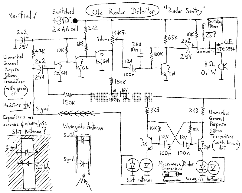
This device is a highly effective capacitive sensor. In North America, it is primarily utilized for detecting wooden beams behind drywall or plaster. This model is preferred over newer designs due to its reliability, as it does not frequently...
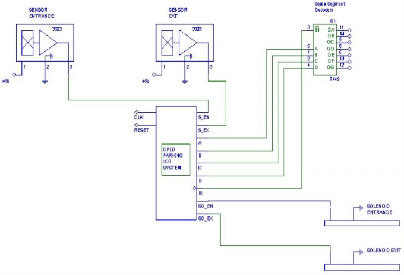
The objective of this project was to create a parking lot management system. The project was divided into five design phases. Throughout the development process, various challenges were encountered, and progress was made compared to the reports from the...
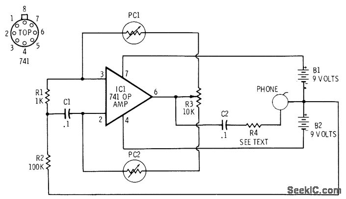
The 741 operational amplifier is configured as an audio oscillator using Radio Shack 276-677 photocells in the feedback circuits. When light strikes photocell PC1, its resistance decreases, resulting in a corresponding decrease in the frequency of the audio tone...

This is an update to Mr. Hareendran's PIR Sensor Security Light circuit. It has a limitation that restricts the relay voltage to approximately 3.3V. While this may work with some 5V relays, it is not compatible with all. The...
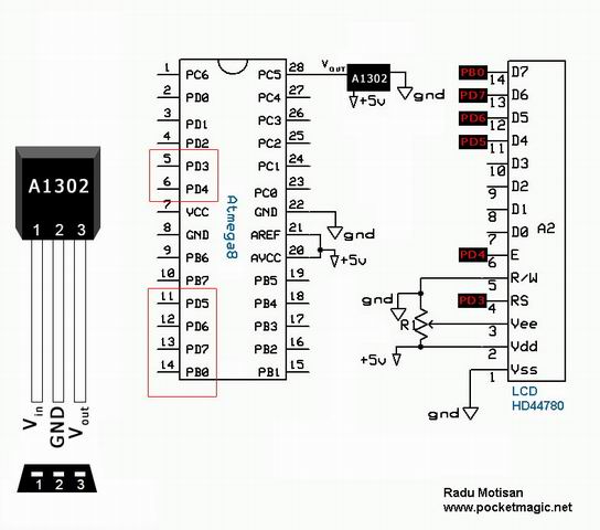
The A1301 and A1302 are continuous-time, ratiometric, linear Hall-effect sensor integrated circuits (ICs). These sensors are designed to provide an accurate voltage output that is proportional to the magnetic field applied. The quiescent output voltage of these devices is...
The provided schematic diagram illustrates an LM741 light/dark sensor circuit, derived from the 741 Op-Amp Tutorial by Tony van Roon. The ECG128/NTE128 transistor can be replaced with any NPN transistor that meets the necessary gain and current specifications for...