
Single Transistor Half-Wave Peak Detector Circuit

The peak detector circuit utilizes a single transistor, typically configured in a common-emitter arrangement, to achieve its functionality. The primary role of the transistor is to amplify the input signal, allowing for the detection of peak values. The circuit also incorporates passive components such as resistors and capacitors, which are essential for setting the time constant and determining the sensitivity of the detector.
In a standard configuration, the input signal is applied to the base of the transistor, which responds by conducting and allowing current to flow through the collector. A diode is often included in the circuit to ensure that the capacitor, which stores the peak voltage, only charges when the input signal exceeds the previously detected peak. This prevents the capacitor from discharging back through the input.
The output of the circuit is taken from the junction of the capacitor and the diode, providing a voltage that corresponds to the peak value of the input signal. By adjusting the values of the passive components, such as the resistor connected to the base, the sensitivity and response time of the peak detector can be tailored to suit specific application needs.
This type of peak detector circuit is particularly useful in audio processing, signal conditioning, and various measurement applications where it is necessary to capture and hold the maximum voltage level of an incoming signal. Overall, the simplicity of the design, combined with the effectiveness of the peak detection, makes this circuit an attractive option for engineers and hobbyists alike.Using only a single transistor and few passive components, you can build a fairly sensitive peak detector. circuit This peak detector circuit is suitable for. 🔗 External reference
Related Circuits
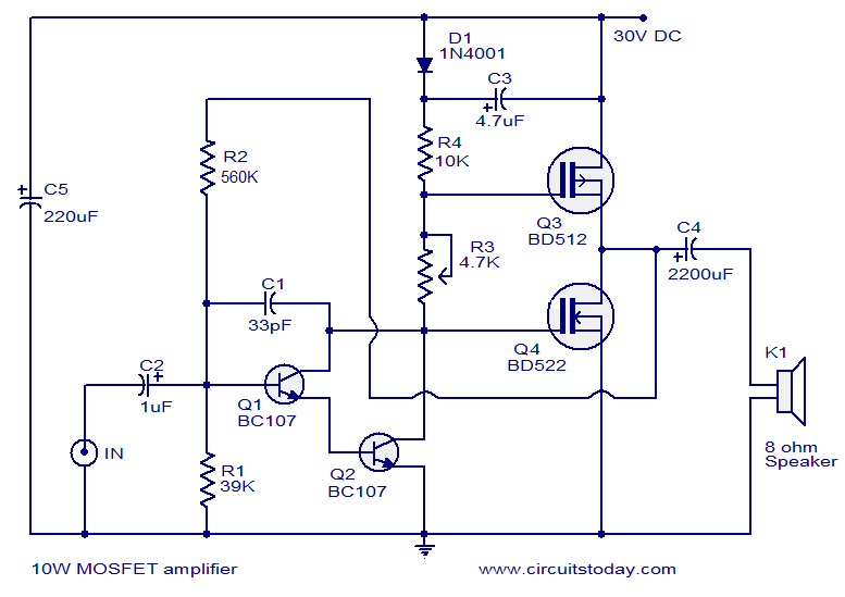
This article lists various types of audio amplifier circuits using MOSFETs. All circuits have been tested in a laboratory environment and have shown satisfactory performance. The amplifier utilizes one transistor, two MOSFETs, and a few resistors and capacitors in...
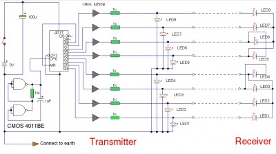
The LAN tester circuit can also test cables such as telephone, coaxial, LAN, and others. This circuit uses LEDs as the main indicator device. The LAN tester circuit is designed to verify the integrity and functionality of various types of...
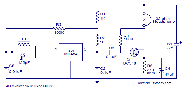
A cost-effective and straightforward AM receiver circuit utilizing the MK484 integrated circuit. The circuit requires minimal external components and operates within a frequency range of 150 kHz to 3 MHz. The MK484 AM receiver circuit is designed for simplicity and...
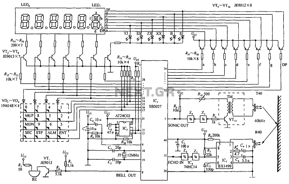
A circuit diagram of an ultrasonic range finder is constructed using a clock with a calendar and the Ultrasonic Ranging IC SB5027. The ultrasonic range finder circuit utilizes the Ultrasonic Ranging IC SB5027, which is designed to measure distances by...
This circuit was designed to detect when a call is incoming in a cellular phone (even when the calling tone of the device is switched-off) by means of a flashing LED. The device must be placed a few centimeters...
This schematic diagram illustrates a water level sensor, detector, and monitor circuit. An alarm is also integrated into this circuit. It is designed to detect any fluid with a resistance below 900K ohms. The water level sensor circuit typically employs conductive...