
3 different Xenon flashing circuits

The Xenon flash circuits from disposable cameras serve as an excellent resource for exploring high-voltage applications in compact electronic systems. Each circuit is designed to efficiently generate a high-voltage pulse necessary for igniting the Xenon gas within the flash tube. The fundamental operation of these circuits typically involves a transformer, a capacitor, and a triggering mechanism.
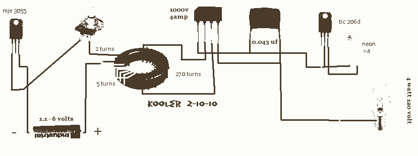
The first circuit, comprised of six building blocks, can be broken down into the following components: a power source, a charging capacitor, a transformer, a switch, a flash tube, and a triggering circuit. The power source, typically a battery, supplies energy to charge the capacitor. The capacitor stores energy and releases it rapidly through the transformer, which steps up the voltage to the kilovolt range needed for the Xenon flash tube.
The modification process requires an old disposable camera, which houses the essential components, along with two additional parts that may include a resistor or diode to enhance circuit performance or modify the triggering mechanism. The implementation of these modifications can lead to improved efficiency, reliability, or functionality of the flash circuit.
The second and third circuits may introduce variations in the design, such as different transformer configurations or alternative triggering methods, allowing for experimentation and learning. These circuits are not only practical for photography but also serve as educational tools for understanding high-voltage electronics and the principles of capacitive discharge.
In conclusion, the exploration of Xenon flashing circuits from disposable cameras offers valuable insights into high-voltage circuit design, with practical applications that extend beyond photography. The modifications and techniques learned through this discussion can be applied to various electronic projects, enhancing skills in circuit design and troubleshooting.This discussion covers 3 different Xenon flashing circuits from disposable cameras. From them, you will learn circuit tricks that have NEVER been shown in any theory book.The first circuit covers 6 BUILDING BLOCKS.You will need an old disposable Flash Camera plus two extra parts to carry out the modifications.. 🔗 External reference
Related Circuits
Second Stage Joule Thief Circuits The second stage Joule Thief circuit is an advanced iteration of the basic Joule Thief design, which is primarily used to extract energy from low-voltage sources, such as depleted batteries. This circuit is particularly effective...

A small biped walker constructed from 2mm plywood, powered by two RC servos. It utilizes the widely available and programmable flash microcontroller PIC16F84. This simple circuit is designed to program the PIC16F84 and similar flash memory components. The project...
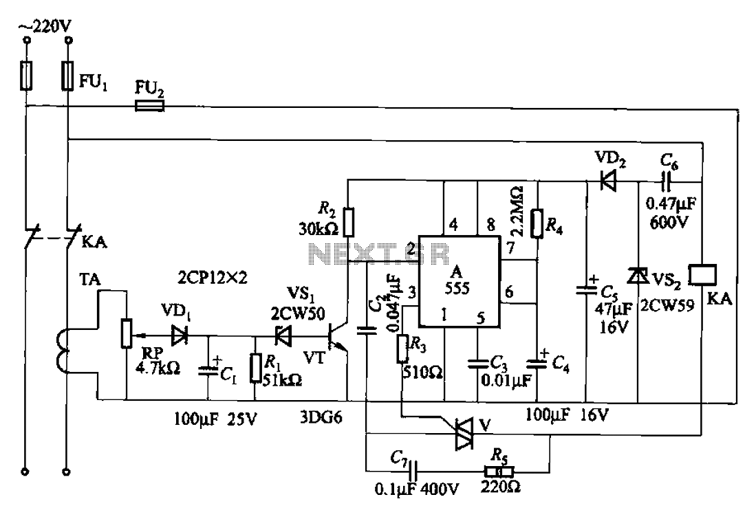
The 555 limit circuit, which is an integrated electrical circuit, is designed to manage large electrical loads. It automatically disconnects power when the load exceeds a predetermined threshold. Once the load is reduced below this threshold, power is restored...
Electrical lines that include lighting circuits originate from the main distribution panel of the installation. Each line consists of three conductors: phase, neutral, and ground. All three conductors extend to the terminal point of each luminaire, and if the...
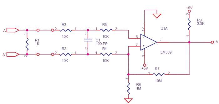
The differential outputs are balanced and designed to drive long lengths of coaxial cable, stripline, or twisted pair transmission lines with characteristic impedances ranging from 50 ohms to 500 ohms. Differential transmission is superior to single-wire transmission as it...
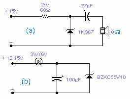
These two circuits are interesting from an academic point of view. Their practical implementation is rather critical and it is not easy to get steady operation. Circuit (a) requires a "cooked" zener: connect it first to a constant current...