
RS232 transceiver circuits

The RS232 transceiver circuits serve as essential interfaces for enabling communication between microcontrollers and various peripheral devices. The MAX232 is a widely utilized component in these applications due to its robust design and ability to convert TTL (Transistor-Transistor Logic) logic levels to RS232 levels, which are necessary for standard communication protocols. The circuit typically consists of multiple capacitors and the MAX232 chip itself, which ensures that the signal integrity is maintained even in electrically noisy environments.
The MAX232 operates effectively with a single +5 V power supply, making it suitable for battery-powered applications and low-voltage systems. The integration of ESD protection ensures that the device can withstand transient voltage spikes, which is critical for maintaining the reliability of the communication link. The dual-channel capability of the MAX232 allows for full-duplex communication, enabling simultaneous transmission and reception of data.
In addition to the MAX232, the DS275 transceiver chip provides an alternative solution for applications requiring a half-duplex communication method. This chip is designed for low-power operation, making it ideal for battery-operated devices where energy efficiency is paramount. The compatibility with RS-232-E signals ensures that it can interface seamlessly with a wide range of devices, further enhancing its utility in various applications.
Overall, the integration of these RS232 transceiver circuits in microcontroller-based systems facilitates reliable communication and expands the functionality of embedded systems, making them essential components in modern electronic designs.There are several RS232 transceiver circuit used for commond communicated between microcontroller and other devices such as PCs or devices rs232. Here is a collection of RS232 transceiver circuits that use well-known for today. The circuit using MAX232, Maxim`s devices. This circuit is very stable and the use of professional design. This device is i nexpensive and it can provide 2-channel RS232. The MAX232 line drivers / receivers for RS-232 and V. 28 communications in harsh environments designed. Each transmitter output and receiver input is protected against 15kV electrostatic discharge (ESD) shocks, can be operated without latchup. It from a +5 V supply voltage. This RS232 transceiver circuit using DS275, a small half-duplex transceiver chip. I Compatible with RS-232-E signals and suitible for low-power serial transmitter / receiver for battery-
🔗 External reference
Related Circuits
Electron trajectories in a conductor are depicted in the diagrams below. When no electric field is present inside a conducting material, electrons move randomly. However, when an electric field is applied, the electric force F = qE induces a...
This self powered interface circuit electrically isolates the TxD and RxD lines from the PC serial port and protects the PC from direct connection to hazardous voltages. The isolator is intended to provide electrical isolation between a computer and...
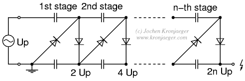
The Greinacher doubler circuit (a) transforms a grounded AC voltage (peak voltage Up) into symmetrical DC voltages of 1x Up each, thus producing 2x Up between outputs. If the input voltage is already symmetrical (e.g. as in an Obit),...
One of the most effective communication methods to be implemented in a digital system is the use of the RS232 serial line. The microcontroller 89S51 is equipped with a UART, allowing it to perform serial communication at RS232 levels...
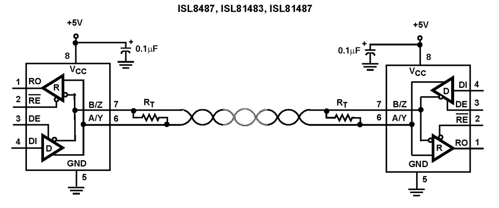
The Intersil RS-485/RS-422 devices are fractional unit load (UL), BiCMOS, 5V powered, single transceivers that comply with both RS-485 and RS-422 standards for balanced communication. This Intersil family is designed for 10% tolerance supplies (4.5V to 5.5V). The ISL81483...
Many applications require low-frequency signal generators that can deliver high-performance, high-resolution signals. This design idea presents a circuit that generates frequencies from 0 to 1 MHz, providing sinusoidal, triangular, and square-wave outputs with frequency resolution better than 0. A...