
Ruby Pulse Laser and Holograms

The ruby laser system is a sophisticated assembly that requires precise engineering to ensure proper functionality and safety during operation. The laser's ability to produce short pulses is critical for capturing dynamic objects in holographic form, which is a significant advantage over traditional laser systems. The design of the trigger circuit is particularly important; it must synchronize with the rotating prism to ensure that the laser light exits the system at the optimal moment. The use of a magnetic pickup provides a reliable method of generating timing signals, while the combination of resistors, capacitors, and timing chips allows for fine-tuning of the delay.
Furthermore, the voltage multiplier circuit is an essential aspect of the system, as it transforms standard voltage levels to meet the requirements of the flashbulb. Each stage of the multiplier contributes to the overall voltage increase, and careful design is necessary to prevent excessive voltage output, which can lead to component failure or safety hazards. The integration of these components into a cohesive system requires careful planning and execution, ensuring that all parts work in harmony to achieve the desired outcome of producing high-quality holograms. Overall, the ruby laser project exemplifies the intersection of advanced electronics and practical application in the field of holography.The ruby laser is a pulse laser with a very short pulse (a few nanoseconds) allowing us to make holograms of many types of objects including objects that normally can`t be used to make holograms. Making holograms with normal beam lasers requires a completely stationary object because if there are any slight vibrations in the object, the hologram w
ill not show an image of the object, but rather will look like sliced bread. However, if the laser pulse is very short, the objects appear to be frozen. Even if an object appears to be moving to us, it will not move any significant distance in the short pulse of the laser. So, we can make holograms of objects such as your hand. This is the main benefit of using a ruby pulse laser to make holograms. Our goal for this project was to get a ruby laser working and hopefully make some holograms. This includes building a trigger circuit to time the flashbulb correctly, building a voltage multiplier to get a high voltage power supply, building a safety containment box, and wiring everything together to make the ruby laser.
Ruby lasers work by exciting a ruby rod, which then emits photons. The high voltage power supply provides energy to a quartz flashbulb in the laser cavity which then emits a brief flash of very bright light. This intense flash excites some of the atoms in the ruby rod to higher energy levels. When the atoms drop energy states, they emit particles of light called photons. These photons bump into other atoms causing them to change energy state and emit photons as well. This continues and the light intensity is quickly amplified. These photons are then directed out one end of the ruby rod and reflected toward a rotating prism. This prism only completes the optical path of the laser(see figure 1) for a very short period of time and for this reason we have a very short pulse of laser light that leaves the laser.
The light that is emitted is all coherent and of the wavelength 694. 3 nm. The component that required the most time and effort was our trigger circuit. This circuit was needed so that we could ensure that when the laser fired, the rotating prism would be aligned allowing the laser light to travel out of the laser. The first thing we needed to do was create a circuit that would strobe an LED at the same frequency as our prism was rotating.
This was achieved by using the signal from the magnetic pickup attached to the rotating prism. Every time that the magnet moved passed the pickup, which was simply a coil of wire, an electrical pulse is sent out to the circuit. We then used these pulses to create an output signal that was the same frequency as the rotating prism.
Then, using a series of resistors and capacitors in combination with a 556 chip, we set up a specifically timed delay so that by viewing the rotating prism with our strobing LED we could carefully align the position of the prism by simply rotating a potentiometer. Since the ultimate goal of this circuit is to fire a flashbulb we need to have one single pulse coming out of our circuit that is timed correctly with the prism.
To accomplish this we added a series of NAND gates and a 74123 so that when a switch was pressed a single, correctly timed pulse would come out. See figure 2 for the complete schematic of our strobe circuit. The next component that was essential in firing our laser was our high voltage power supply. This was needed in order to fire out flashbulb. Normal rectified line voltage is only 170V and we needed 880V, so in order to achieve this voltage we built a voltage multiplier circuit.
A voltage multiplier circuit sequentially steps up the voltage in various stages using a combination of capacitors and diodes. For our multiplier we used 6 stages thinking that this would give us the voltage needed. This however, provided us with too much voltage, approximately 1900V, so we had to tap off of the 4th stage which gave us approximately 8
🔗 External reference
Related Circuits
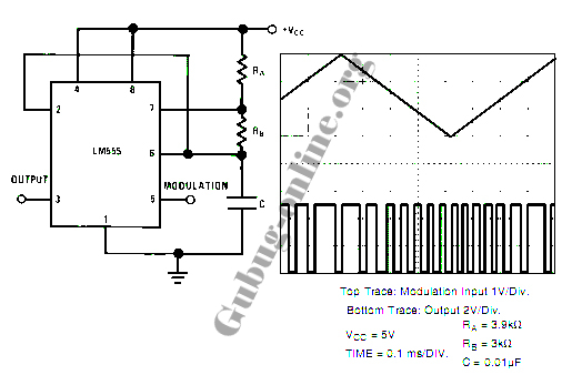
This design circuit for a pulse position modulator can be easily constructed using a 555 integrated circuit (IC). The pulse position modulator modulates the on-period while maintaining a fixed off-period. The circuit utilizes the 555 timer IC in astable mode...

The circuit is a temperature-to-pulse-width converter. The LM3524 is used to convert the output of an LM135 temperature transducer into a pulse width that can be measured by a digital system, such as a microprocessor-controlled data acquisition system. In...

This circuit includes an amplifier and a video detector along with a secondary subcarrier detector for synchronization recovery. A pulse-former circuit modulates the gain of the main channel, enhancing it during synchronization intervals. Additionally, there is a provision for...
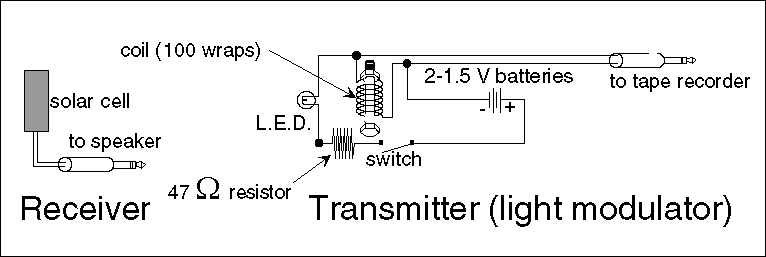
Electromagnetic radiation is utilized in communication systems. Common forms of electromagnetic radiation include radio waves, microwaves, and television signals. Visible light, which is also a type of electromagnetic radiation, can be employed for signal transmission, leading to the development...
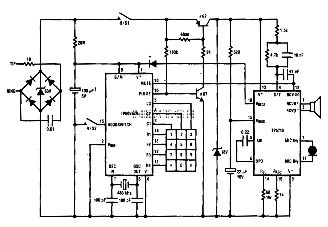
The TP5700 or TP5710 can reduce the number of components required to build a pulse-dialing telephone. The typical current source can be eliminated by utilizing the VREG1 output to power a TP50982A low-voltage (1.7 V) pulse dialer through a...

The UC3842, UC3843, UC3844, and UC3845 series of oscillators can generate synchronization pulses without requiring numerous external components. The following circuit illustrates the Sync Pulse Generator Circuit Diagram for the UC3842/3/4/5. This sync pulse circuitry is capable of operating...