
Rugged lamp driver

The circuit utilizes a Darlington transistor configuration, which is known for its high current gain and is particularly suitable for applications requiring the control of higher power loads. The use of a 200 mA, 60 V DC filament lamp indicates that the circuit is intended for moderate power applications, where efficient control is necessary.
The optical coupler (IC2) serves to electrically isolate the control signal from the high-voltage circuit, enhancing safety and preventing potential damage to the control circuitry. The Zener diode (ZD1) plays a crucial role in maintaining a consistent reference voltage, which is essential for the reliable operation of the optocoupler, ensuring that it switches appropriately in response to the logic signal.
The design includes an emitter resistor (R5), which is integral for stabilizing the current through the Darlington transistor. This resistor aids in setting the operating point of the transistor and helps prevent thermal runaway by providing feedback. The circuit's ability to switch on the lamp effectively when the control signal is present demonstrates its suitability for applications such as lighting control in various electronic systems.
Overall, this circuit exemplifies a practical approach to controlling high-power loads with low-power logic signals, ensuring both functionality and safety in its operation.This circuit is capable of driving filament lamps of nominal rating 200 mA at 60 V dc from a CMOS logic signal. The lamp or load is connected in series with the Darlington transistor TR1 and emitter resistor R5. The Zener diode ZD1 establishes a soft reference voltage on the collector of the optical coupler IC2.
When the logic control signal from the processor switches the optocoupler on via IC1, base drive is applied to TR1 and the lamp is switched on.
Related Circuits
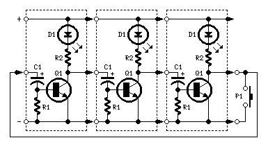
Very simple, versatile modular design. The purpose of this circuit was to create a ring in which LEDs or Lamps illuminate sequentially. Its main feature is a high versatility: you can build a loop containing any number of LEDs...
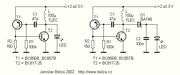
The article describes a simple and very cheap to drive white, blue or UV LEDs, used for example in small lamps and testers. The cost of components shall not exceed CZK 10. Converters for white LED has been on...

This ultra-bright white LED lamp operates on 230V AC with minimal power consumption. It is suitable for illuminating VU meters, SWR meters, and similar applications. The ultra-bright white LED lamp designed for 230V AC operation offers significant advantages in terms...

To simplify the driver circuit, a multiplexer circuit can be utilized as a solution. With this multiplexed BCD decoder, only one BCD is required. A multiplexer (MUX) is an essential component in digital circuits, allowing multiple input signals to be...
A battery switch-over circuit is being developed, consisting of two parallel lanes as depicted in the circuit diagram. The operational voltage range spans from 3V to 12V. Only one lane should be active at any given time, which is...

A school drama required lamps that automatically turned on and off in sync with the spotlights. The lamp switching system needed to be wireless, durable, reliable, simple, and cost-effective. With the stage and spotlights turned off, minimal light reaches...