
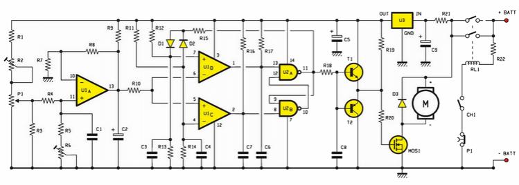
Run/Stop Relay Circuit

In motor-driven applications, safety mechanisms are essential to prevent accidents and ensure the well-being of operators and equipment. Various strategies can be employed to enhance safety in these systems.
One common approach is the implementation of emergency stop (E-stop) circuits, which allow operators to quickly halt motor operation in case of an emergency. These circuits typically involve a normally closed push-button switch that, when pressed, interrupts the power supply to the motor, effectively stopping its operation.
Another important safety feature is the use of overload protection devices, such as thermal relays or fuses. These components monitor the current flowing to the motor and can disconnect the power if the current exceeds a predetermined threshold, preventing damage to the motor and reducing the risk of fire.
Additionally, safety interlocks can be integrated into the motor control circuitry. These interlocks ensure that the motor cannot start unless certain conditions are met, such as the closure of safety guards or the presence of an operator at a safe distance.
Furthermore, the use of variable frequency drives (VFDs) can enhance safety by providing soft start and stop capabilities, reducing mechanical stress on the motor and connected equipment. VFDs can also include built-in safety features that monitor motor performance and provide feedback to the control system.
In summary, implementing effective safety measures in motor-driven applications is crucial for minimizing risks and enhancing operational reliability. The integration of E-stop circuits, overload protection, safety interlocks, and advanced motor control technologies contributes to a safer working environment in industrial settings.Safety is a major concern in a good many motor-driven applications. This is true in industrial applications where motion starts when power is applied and e.. 🔗 External reference
Related Circuits
A circuit that utilizes one cycle of alternating current (AC) to produce direct current (DC). A half-wave rectifier circuit generates DC from either the positive or negative cycle of the AC input, but not both. It is important to...

RTD sensors are measured using a precision 24-bit analog-to-digital converter (A/D) that includes a built-in programmable gain amplifier. The connections for 2-wire, 3-wire, and 4-wire RTDs are illustrated. This setup facilitates the connection and measurement of RTDs with amplifiers and...

A composite pipe can be reduced to facilitate the adjustment of the control current within the tube. Composite pipes are often utilized in various applications due to their lightweight, strength, and flexibility. When discussing the reduction of a composite pipe,...
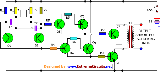
This is a simple and cost-effective inverter designed to power a small soldering iron (25W, 35W, etc.) in situations where a mains supply is unavailable. The circuit utilizes eight transistors. The inverter circuit operates by converting DC voltage from a...
An electric scooter and E-Bike PWM speed controller circuit has been constructed. However, the oscillator is not functioning as intended. The printed circuit board has been checked and is confirmed to be in good condition, including all resistors. The electric...

This circuit provides an initial voltage of 2.5V per cell to quickly charge a car battery. The charging current decreases as the battery charges, and when the current drops to 180 mA, the charging circuit reduces the output voltage...