
Inverter Circuit For Soldering Iron

The inverter circuit operates by converting DC voltage from a battery source into an AC voltage suitable for the operation of small soldering irons. The design typically consists of an oscillator stage that generates a square wave signal, which is then amplified and transformed into a higher voltage AC signal.
The use of eight transistors in the circuit serves multiple purposes. Firstly, they are arranged in a push-pull configuration to drive the transformer, which steps up the voltage to the required level for the soldering iron. The oscillator circuit is usually built using two transistors that alternate their conduction states, creating a square wave output. This output is fed into the base of the push-pull transistors, driving them into saturation and allowing current to flow through the primary winding of the transformer.
The transformer plays a critical role in this inverter design. It not only steps up the voltage but also provides isolation between the DC source and the AC output, enhancing safety during operation. The secondary winding of the transformer is connected to the soldering iron, delivering the necessary voltage and current for its operation.
Additional components may include resistors, capacitors, and diodes, which help stabilize the circuit, filter noise, and protect against voltage spikes. Proper heat dissipation mechanisms should be considered for the transistors, as they may generate significant heat during operation.
Overall, this inverter circuit is an effective solution for powering small soldering tools in environments without access to mains electricity, making it a valuable addition to portable soldering setups.Here is a simple but inexpensive inverter for using a small soldering iron (25W, 35W, etc) In the absence of mains supply. It uses eight transistors and a.. 🔗 External reference
Related Circuits
The inverter circuit is appreciated, and there is a request for detailed functionality of IC1 and IC2 in the 3000W inverter circuit. The individual expresses gratitude for the schematic diagram and seeks assistance in building the transformer, including specifications...
This site addresses a range of subjects pertaining to circuits and electronics. Some of the topics discussed on this site include: * Alternating Relay Switch * Photoswitch Relay. The site serves as a comprehensive resource for understanding various electronic components...
The amplification of this circuit is approximately 12,000 times, with a bandwidth ranging from 0.5 to 14 MHz. The input resistance is 700 ohms, while the output resistance is 35 ohms (measured at 5 MHz). The output noise level...
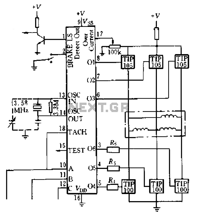
Four application examples are presented in the figure, focusing on a three-phase brushless DC motor used in Winchester disk drives with an operating speed of 3600 RPM. Although the original design specifies an operating speed of 3600 RPM, alternative...
Wibowa Chou from IR discusses the benefits of fourth-generation IGBTs compared to MOSFETs, particularly in the context of a practical solar inverter application. Fourth-generation Insulated Gate Bipolar Transistors (IGBTs) offer significant advantages over Metal-Oxide-Semiconductor Field-Effect Transistors (MOSFETs) in various applications,...
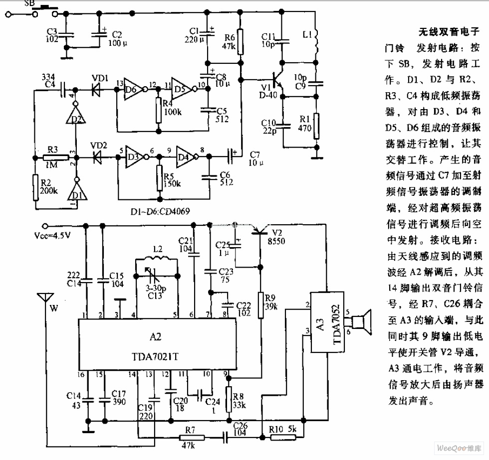
The transmitter circuit is activated by pressing the SB button. Components D1, D2, R2, R3, and C4 form a low-frequency oscillator that controls an audio oscillator made up of D3, D4, D5, and D6, allowing them to operate alternately....