
Running Message DisplayCircuit Based On The CD401IC

The Running Message Display Circuit utilizes the CD401 integrated circuit, which is a versatile component in digital electronics. This circuit is designed to control a series of light-emitting diodes (LEDs) to create a scrolling text effect, making it suitable for various display applications such as advertising, information boards, or decorative signage.
The circuit typically consists of a microcontroller or a timer circuit that interfaces with the CD401 IC. The CD401 is a binary counter that can drive multiple outputs, making it ideal for controlling a sequence of LEDs. The LEDs are arranged in a matrix or a linear configuration, depending on the design requirements.
In a standard implementation, the microcontroller sends data to the CD401, which then activates the LEDs in a specific sequence to create the desired message. Resistors are used in series with the LEDs to limit current and prevent damage. Additionally, a power supply circuit is included to ensure that the entire system operates within the required voltage and current specifications.
The advantages of using LEDs in this circuit include their low power consumption, long lifespan, and compact size, which allows for more flexibility in design and installation. The use of the CD401 IC simplifies the circuit design by reducing the number of discrete components needed, thereby enhancing reliability and ease of assembly.
Overall, the Running Message Display Circuit is an effective solution for creating dynamic visual displays using LED technology, driven by the capabilities of the CD401 integrated circuit.Running Message Display Circuit Diagram. This circuit Based On The CD401IC. Fetures: Light emitting diodes are advantageous, cos smaller size, .. 🔗 External reference
Related Circuits
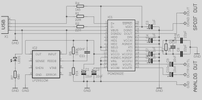
This is a high-quality preamplifier circuit with a built-in USB DAC designed for the Leachamp power amplifier. The schematic is derived from the PCM2902 datasheet. The circuit includes a DAC and ADC, SPDIF output and input, and an HID...

The concept involves using infrared light that is reflected by a disc, except for a dark red line. The sensor receives the reflected light, allowing the Arduino to track the number of revolutions. The infrared sensor is tuned to...

This post presents the implementation of a free-running counter using the C programming language for the PIC16F84A microcontroller. The code is structured to... The PIC16F84A microcontroller is a widely used device in various embedded applications, characterized by its 8-bit architecture...

The 22-turn coil is positioned above the 84-turn coil. Connecting this coil significantly impacts performance. Testing with a 1 kW heater yielded better results; however, prolonged use may lead to failure. The heater's wire typically does not glow as...

This circuit diagram illustrates a linear FM booster and RF amplifier utilizing the Philips 2N4427 transistor. The RF amplifier is designed to enhance the performance of small FM transmitters and bugs, employing two Philips 2N4427 transistors, delivering approximately 1...

Upon entering the password, the application, in this case "LED," will illuminate. In this digital locking system project, the interfacing of a keypad and a 16x2 LCD with a microcontroller will be explored, along with the accompanying code. This...