
1w fm booster based 2n4427

The circuit operates on the principle of amplifying RF signals, making it suitable for applications in FM transmission. The use of two 2N4427 transistors in a push-pull configuration enhances the overall gain and efficiency of the amplifier. The transistors are capable of handling the power requirements while maintaining linearity, which is critical for FM signals to avoid distortion.
The design specifies a power supply of 12 Volts, with a recommended current rating of 500mA, ensuring that the circuit operates within safe limits. Exceeding the voltage beyond 15 Volts is cautioned against, as it can lead to thermal runaway and eventual failure of the transistors. The amplifier's gain of 15 dB is optimal for boosting signals in the specified frequency range, which is particularly useful for FM broadcasting applications.
The inductors L4, L5, and L6 play a crucial role in tuning the amplifier to the desired frequency range. These air-core coils, constructed with 1mm wire, provide the necessary inductance while minimizing losses associated with core materials. The choice of 8 turns for each coil is a balance between size and inductance, ensuring compactness without compromising performance.
This circuit can be assembled on a standard PCB, with attention to layout to minimize parasitic inductance and capacitance. Proper grounding techniques and decoupling capacitors are recommended to ensure stable operation. Overall, this FM booster circuit is an effective solution for enhancing the range and clarity of FM transmission, making it a valuable project for electronics enthusiasts and professionals alike.This is the circuit diagram of linear FM Booster / RF amplifier based 2N4427 Philips transistor. The RF Amplifier is for boosting small fm transmitters and bugs. It use two Philips 2N4427 and its power is about 1Watt. At the output you can drive any linear with BGY133 or BLY87 and so on. Its power supply has to give 500mA current at 12 Volts. More voltage can boost the distance but the transistors will be burned much earlier than usual. ! In any case do not exceed the 15Volts. The Amp offers 15 dB in the area of 80Mhz to 110 Mhz. L4, L5, and L6 are 5mm diameter air coils, 8 turns, with wire 1mm wire diameter. This is an easy project, but will give you great results. 🔗 External reference
Related Circuits
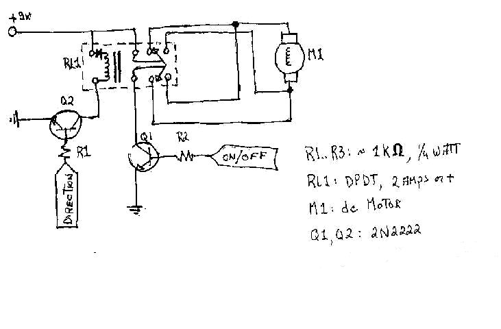
To create the circuitry described, a computer software capable of controlling a parallel port is required, with an estimated cost of approximately $30. For instance, a transistor (model number 2N2222) is priced around $0.50, while a DPDT relay costs...
The following circuit illustrates a Dancing LEDs electronic circuit diagram. This circuit is based on the LM358 integrated circuit. Features: IC1A amplifies the signal. The Dancing LEDs circuit utilizes the LM358 operational amplifier to create a visually appealing light display....

MP3 players have gained immense popularity, especially the compact memory-stick format, which allows for easy portability and personal music enjoyment on the go. However, when sharing music with others, these players often lack sufficient power. A solution to this...
A DC-to-DC step-up converter is typically implemented using a transformer, which converts DC voltage to AC voltage, steps it up with the transformer, and then rectifies and filters the output to achieve a higher DC voltage. However, a voltage...

Microcontroller-Based Accelerometer Project. Just as a speedometer is a device that measures speed, an accelerometer is a device that measures acceleration. The microcontroller-based accelerometer project utilizes an accelerometer sensor to detect changes in velocity and orientation. This project typically involves...
This project automates home appliances via a Bluetooth-enabled PC. A USB Bluetooth adapter is utilized on the PC side, while a Serial Bluetooth module is employed for communication. This project involves the integration of a Bluetooth-enabled PC with home appliances...