
THREE INPUT VIDEO MIXER

In radar systems, the integration of various signal components is crucial for accurate data representation and operational effectiveness. The described circuit serves as a versatile combination unit that allows for the merging of three specific inputs: radar video, beacon signals, range markers, range strobe, and azimuth markers. Each of these components plays a significant role in enhancing the radar system's functionality.
Radar video provides the primary visual information about detected objects, while beacon signals are essential for identifying specific targets or areas of interest. Range markers and range strobe signals assist in determining the distance to objects, contributing to the overall situational awareness. Azimuth markers indicate the direction of targets, which is vital for navigation and targeting applications.
The circuit is likely designed to handle analog signals, ensuring minimal distortion during the combination process. It may incorporate operational amplifiers for signal amplification and mixing, along with filters to eliminate unwanted noise. The selection of components would be critical to maintain signal integrity, especially in high-frequency applications typical of radar systems.
Furthermore, the circuit may include adjustable parameters to prioritize certain signals over others, allowing for flexibility based on operational requirements. This adaptability is essential in dynamic environments where the radar system must respond to varying conditions and threats.
Overall, this combination circuit is a fundamental element in radar technology, facilitating the effective integration of multiple signal types to enhance the performance and reliability of radar systems in various applications.Used in radar systems for combining any three of the following: radar video, beacon, range markers, range strobe, and azimuth markers. -NBS, "Handbook Preferred Circuits Navy Aeronautical Electronic Equipment, " Vol. 1, Electron Tube Circuits, 1963, p N4-1. 🔗 External reference
Related Circuits
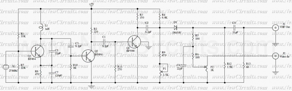
This compact circuit transmitter processes audio signals from a table or microphone, as well as video signals from a camera, DVD, or video cassette. It can transmit these signals directly from a computer over a free VHF channel. The...
This device uses the second method, which requires about 100 times less parts, but adds motion detection to switch cameras. The usual way to detect motion is to store a complete video frame and then look for changes on...
When configured as an input, there is a subtle issue. If the input has its pull-up enabled, it may interfere with the circuitry that expects to see an analog-to-digital (A/D) input. Conversely, if the pull-up is not enabled, the...
This circuit is a RF modulator which can be used for modulating of video signals. The P1 controls the Light and the P2 controls the contrast of video signal. The RF modulated output signal can be received on the...
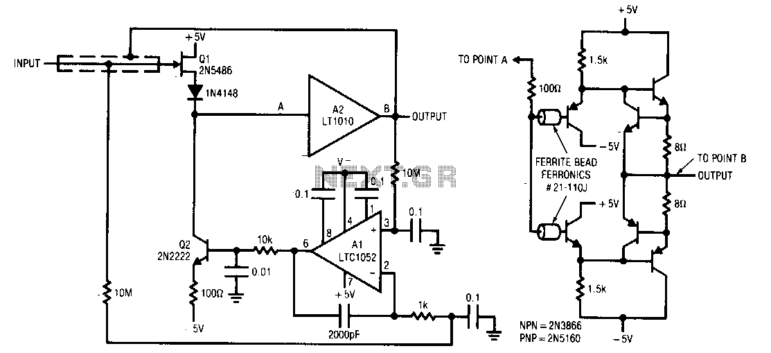
Q1 and Q2 form a simple, high-speed FET input buffer. Q1 operates as a source follower, while Q2 serves as a current-source load that regulates the drain-source channel current. The LT1010 buffer is utilized to provide output drive capability...
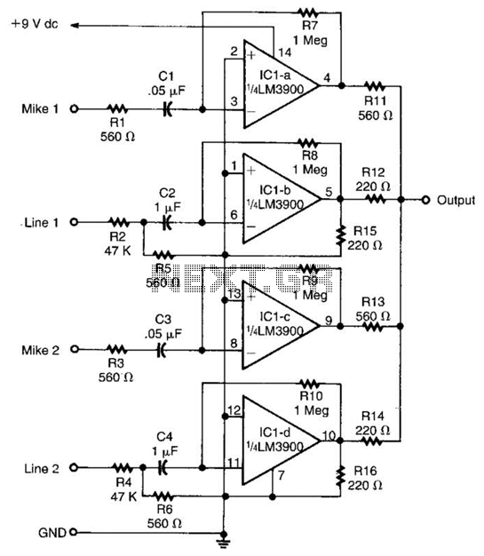
Designed around an LM3900 quad op amp, this mixer combines two line inputs and two microphone inputs, summing them at the output terminal. Resistors R7 through R10 can be adjusted to vary the gain, approximately +23 dB. The mixer circuit...