
Sample and Hold Circuit Using CA3140 Op-Amp

The sample-and-hold circuit is a crucial component in analog-to-digital conversion systems, allowing for the temporary storage of analog signals for subsequent processing. This circuit captures the voltage of an input signal at a specific moment and holds it steady for a defined period, enabling accurate measurements.
In this particular design, the CA3140 operational amplifier serves as the readout amplifier, providing high input impedance and low output impedance, which is essential for interfacing with the memory capacitor. The CA3080A, a current feedback amplifier, is incorporated to enhance the performance of the circuit, particularly in terms of speed and bandwidth.
The operation of the sample-and-hold circuit can be divided into two phases: the sample phase and the hold phase. During the sample phase, the circuit captures the input voltage, which is then stored on the memory capacitor. The switch controlling this phase is typically a high-speed analog switch that ensures minimal charge injection and distortion.
Once the sample phase is complete, the circuit transitions to the hold phase. In this phase, the switch opens, isolating the memory capacitor and maintaining the voltage level for the duration of the hold time. The output from the CA3140 can then be processed or fed into an analog-to-digital converter for further analysis.
The choice of components, such as the CA3140 and CA3080A, reflects a focus on achieving high accuracy and stability in the circuit operation. The design also considers factors like leakage currents and capacitor dielectric absorption, which can affect the hold time and overall performance of the circuit. Proper layout and component selection are essential to minimize noise and ensure reliable operation in various applications.The schematic diagram below shows a very simple sample-and-hold circuit using the CA3140 as the readout amplifier for the memory capacitor. The CA3080A is used. 🔗 External reference
Related Circuits
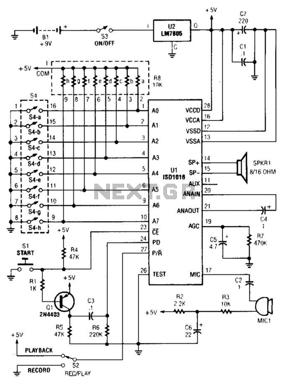
The personal message recorder is based on the ISD1016 CMOS voice messaging system, eliminating the need for complex and costly analog-to-digital and digital-to-analog conversion circuits. A functional block diagram of the ISD1016 is available. The ISD1016 integrates all necessary...

This electronic circuit, based on the CD4017 and logic gates, activates a relay when four keys are pressed in the correct sequence, returning to the initial state afterward. The circuit utilizes the CD4017 decade counter, which is designed to count...
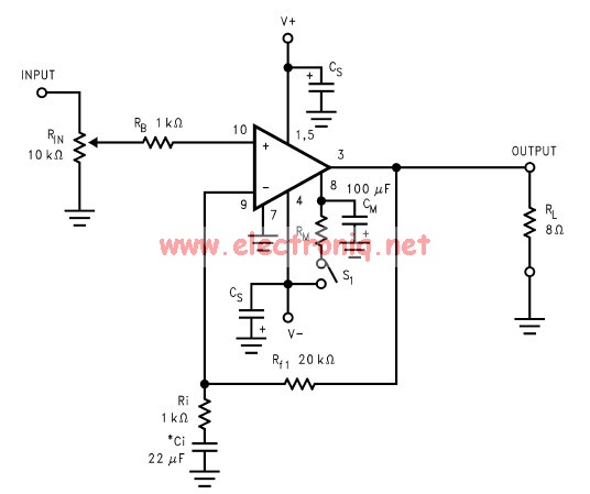
The LM3886 amplifier electronic circuit project is designed to deliver 68W of continuous average power into a 4-ohm load and 38W into an 8-ohm load with a total harmonic distortion plus noise (THD+N) of 0.1% across the frequency range...
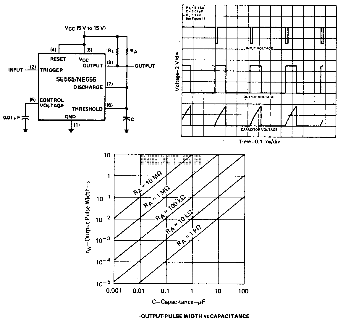
When the output is low, applying a negative-going pulse to the trigger input sets the flip-flop (Q goes low), driving the output high and turning off component 1. Capacitor C is then charged through resistor Ra until the voltage...
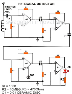
A simple electronic circuit project is presented that can be constructed by any school student for display at a school science fair. The proposed circuit is a high-gain operational amplifier (op-amp) amplifier designed to detect the slightest RF disturbances...
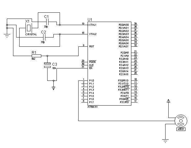
The control signals for the motor's rotation are generated by an 8051 microcontroller. For foundational concepts and information about a servo motor, refer to the article on Servo Motors. The source code utilized is based on the AT89S51 microcontroller....