
Sawtooth Signal Generator

This sawtooth wave generator circuit is designed to produce a continuous sawtooth waveform, which is characterized by a linear rise followed by a rapid fall. The circuit operates by charging a capacitor through a resistor, allowing the voltage across the capacitor to increase gradually. Once the voltage reaches a predetermined threshold (the base-emitter voltage of the PNP transistor), the PNP transistor turns on, allowing current to flow and triggering the NPN transistor. This action creates a feedback loop that rapidly discharges the capacitor, resulting in the characteristic sawtooth waveform.
The synchronization output at output 2 is crucial for applications where timing is essential, as it provides a reference point for other circuits that may need to align their operation with the sawtooth waveform. The frequency of approximately 57 Hz can be adjusted by varying the resistor and capacitor values, allowing for flexibility in applications that require different frequency settings.
Additionally, the pulse generator circuit included in the schematic serves a dual purpose, producing square wave pulses that can be used in various timing and control applications. The adjustable duty cycle allows for customization of the output waveform, which is beneficial in applications requiring specific timing characteristics.
The square-wave oscillator circuit utilizing the LP165/365 comparator is notable for its simplicity and effectiveness. The choice of timing components directly influences the frequency of oscillation, making it essential to select appropriate resistor and capacitor values to achieve the desired output frequency.
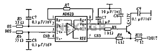
Signal tracing, as mentioned, is an invaluable technique in diagnosing issues within electronic circuits. By injecting test signals and monitoring the output at various points, technicians can isolate faulty components or sections of the circuit, facilitating efficient troubleshooting and repair. This method is particularly advantageous in audio electronics, where precision and clarity of signal are paramount.This sawtooth wave generator gives not only the sweep signal at out 1, but also a synchronization output at out 2 when the sawtooth fly back and begin sweeping. The frequency formula of this sawtooth wave signal is: Remember that the real frequency might be slihgtly different from the formula since the components tolerance in their value.
Using th e formula, the frequency of this sawtooth wave signal would be around 57Hz, using the component values as shown in the schematic. Generating sawtooth wave signal can be implemented using several ways, and one of the very popular method is by using constant current source to charge a capacitor.
If you`ve seen many method that use an SCR or its bipolar transistor Continue reading †’. In the figure a, the capacitor is slowly charged through resistor R and finally after reaching the base-emitter voltage of PNP transistor, the PNP transistor begin conducting and activate the NPN transistor. The activation of NPN transistor is positively fed Continue reading †’. Pulse generator circuit shown in the schematic diagram below produces square wave pulse with adjustable duty cycle/active factor.
The benefits of using this circuit are low components count and high stability of its output frequency. The frequency of this pulse Continue reading †’. The circuit shown in this schematic diagram is a square-wave oscillator circuit. The main component of this oscillator circuit is LP165/365 comparator. As timing component, it uses capacitor and resistor to determine the frequency operation, generating square waves signal.
Here Continue reading †’. Signal tracing is a method to find failure section of electronic circuit. This method is very common in troubleshooting audio electronics, since the tool for injection and monitoring will be very simple and cheap. The tracing method is done by Continue reading †’. 🔗 External reference
Related Circuits
this tone generator can be used to control your robot. you will need to use the tone decoder for this. to widen the range, higher or lower - substitute a higher, or lower valued capacitor for c1. for frequencies...
The High Speed Function Generator was published in the professional electronics section of the Aug 1996 issue of Electronics Australia, and has proven to be extremely popular. The kit is no longer available from any of the kit suppliers. The...
Marx Generators are commonly utilized in pulsed power and high voltage applications to produce a high peak voltage pulse. The fundamental principle behind these generators involves charging several capacitors in parallel, followed by closing switches to connect them in...
The AD623 is an integrated 3-way amplifier that can operate with either a single or dual supply. It features high common-mode rejection ratio (CMRR) and low voltage drift, along with programmable gain control via an external resistor. All components...
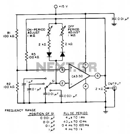
The pulse repetition rate is determined by adjusting switch SI to the desired position, and this rate remains relatively constant even when the resistors that control the on-period and off-period are modified. Resistors R1 and R2 set the biasing...
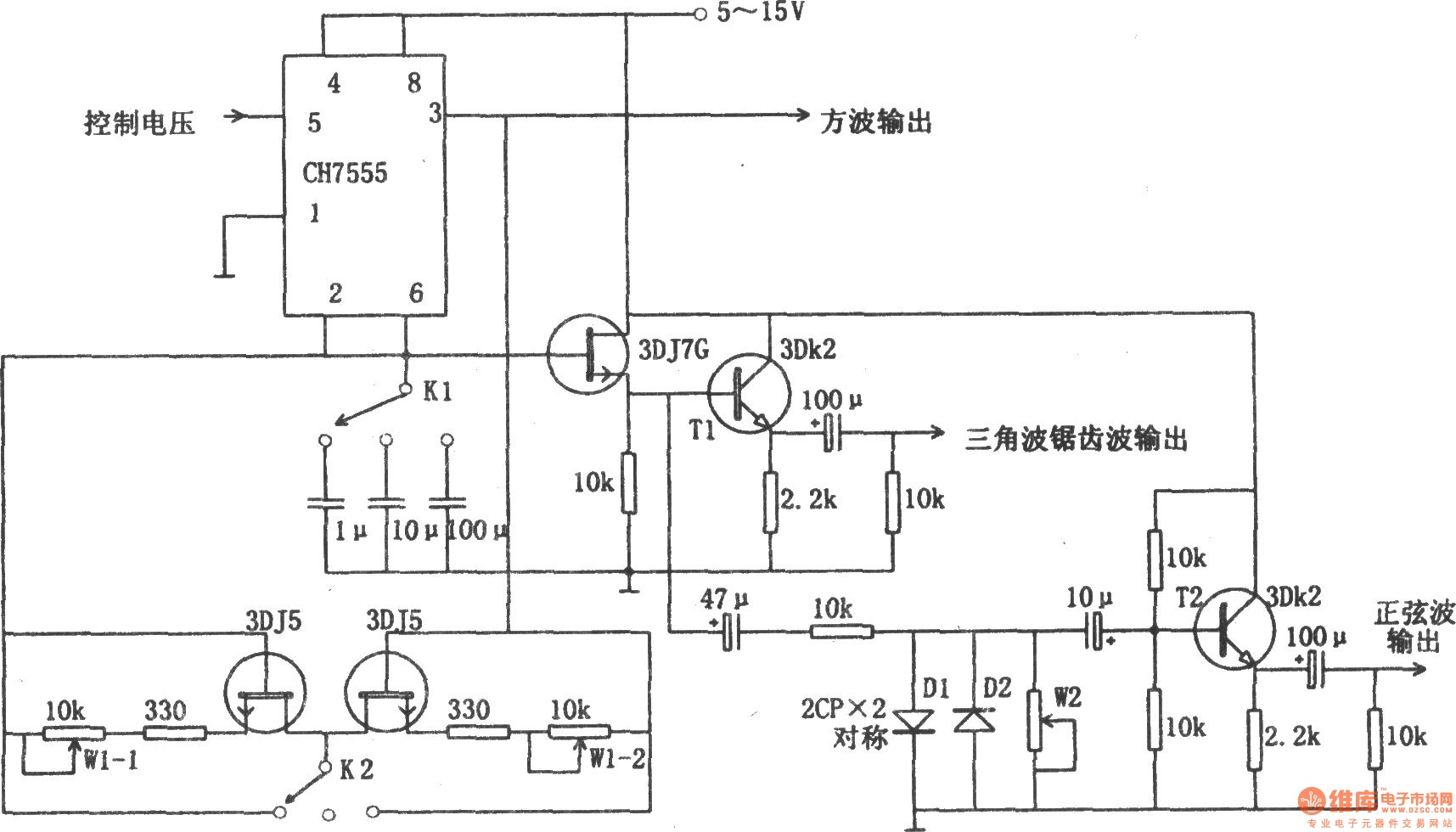
The chart illustrates a function generator circuit utilizing a 555 timer. This circuit includes a CH7555 timer along with several transistors and RC components. It is capable of generating triangle waves, square waves, sine waves, sawtooth waves, and square...