
Pulse generator as astable multivibrator

The circuit utilizes a pulse width modulation (PWM) technique to generate a stable pulse repetition rate. The switch SI allows for the selection of different pulse rates, which are crucial in applications such as signal modulation, timing applications, and control systems. The design ensures that the pulse repetition rate remains consistent despite variations in the on-period and off-period resistances, indicating a robust design that can adapt to different operational conditions without significant drift in performance.
Resistors R1 and R2 play a vital role in establishing the operating point of the CA3130 operational amplifier, ensuring that it operates within its linear region. By biasing the amplifier to the midpoint of the supply voltage, the circuit can efficiently process the input signals, thus improving the overall performance of the PWM output. The feedback resistor R3 is essential for controlling the gain of the operational amplifier, which directly influences the width of the output pulses. Adjustments to R3 can fine-tune the output signal characteristics, allowing for precise control over the pulse width and, consequently, the overall behavior of the circuit.
This configuration is commonly used in various electronic applications, including motor control, LED dimming, and audio signal modulation, where accurate timing and pulse generation are critical. The stability of the pulse repetition rate, in conjunction with the adjustable resistors, provides flexibility for designers to tailor the circuit to specific requirements while maintaining reliable operation across a range of conditions. The pulse repetition rate is selected by positioning SI to the desired position and the rate remains essentially constant when the resistors which determine on-period and off-period are adjusted. Resistors Rl and R2 bias the CA3130 to the mid-point of the supply-voltage, and R3 is the feedback resistor.
Related Circuits
The circuit below is a one-shot multivibrator, also referred to as a monostable multivibrator or timer. The primary function of this circuit is to generate a single output pulse in response to an input trigger. The one-shot multivibrator is a...
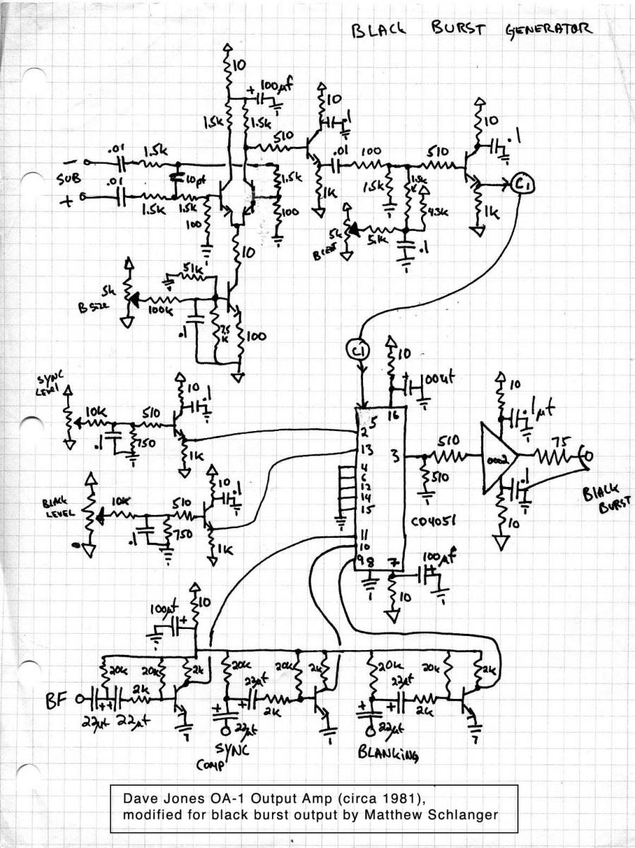
CMOS analog multiplexers are commonly utilized in electronic circuits for various applications. This document presents a modified circuit based on a design by Dave Jones, aimed at constructing a black burst generator. Sync signals are essential in video systems...
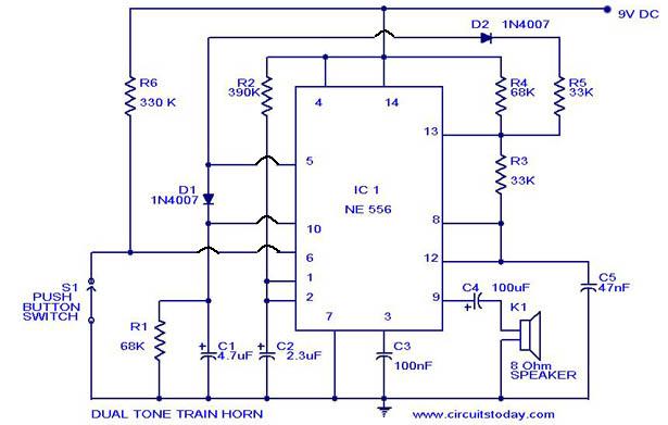
A dual-tone model train horn/sound generator/simulator circuit can be created using two NE 555 timers connected in cascade. However, the circuit diagram presented is designed with the NE 556 integrated circuit, which essentially comprises two 555 timers in a...

The Supertex HV7370 is a four-channel, high-speed, high-voltage ultrasound transmitter damper, while the HV748 is a four-channel, high-speed, high-voltage ultrasound transmitter pulser. Both integrated circuits (ICs) are intended for medical ultrasound imaging applications and can also be utilized as...
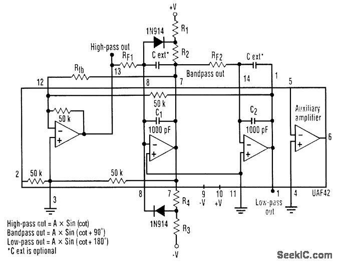
A three-phase sine-wave oscillator can be constructed using a single UAF42 state variable filter, along with a few resistors and diodes. The circuit provides three output nodes: high-pass output, bandpass output, and low-pass output. The signals at the bandpass...

The hobby circuit described utilizes a unique approach to generate approximately 12,000 volts with a current of about 5 µA. It employs two silicon-controlled rectifiers (SCRs) that form dual pulse generator circuits. These SCRs discharge a 0.047 µF capacitor...