
20MHz High Speed Function Generator

The High Speed Function Generator is designed to produce a variety of waveforms, including sine, square, triangle, and sawtooth, with a high degree of accuracy and stability. The circuit typically employs operational amplifiers (op-amps) for waveform generation, utilizing feedback and RC timing networks to define the frequency and shape of the output signals.
The core of the function generator may include a phase-locked loop (PLL) for frequency stabilization, ensuring that the output waveform maintains a consistent frequency over varying load conditions. Additionally, a microcontroller or a dedicated frequency synthesizer IC might be used to allow for precise frequency adjustments and digital control over waveform parameters.
Output stages are usually designed to drive loads directly, with considerations for output impedance to match typical test equipment or circuits. Protection features may be included to prevent damage from overvoltage or excessive current draw.
In terms of power supply, the function generator often operates from a dual supply voltage, such as ±12V or ±15V, to accommodate the op-amps and other active components, ensuring sufficient headroom for signal swing.
Overall, the High Speed Function Generator serves as a versatile tool in both laboratory and field applications, providing engineers and technicians with reliable waveform generation capabilities for testing and development purposes.The High Speed Function Generator was published in the professional electronics section of the Aug 1996 issue of Electronics Australia, and has proven to be extremely popular. The kit is no longer available from any of the kit suppliers. 🔗 External reference
Related Circuits
The original scale on the voltmeter ranged from 0 to 30 volts. A new scale was created by removing the old scale from the meter and scanning it into a graphics editing software on a computer. The old numbers...
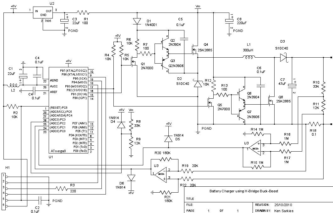
The buck-boost converter is valuable when the output and/or input voltages fluctuate significantly, necessitating the use of a buck converter at times and a boost converter at others. An example, which will be elaborated on in a future project,...
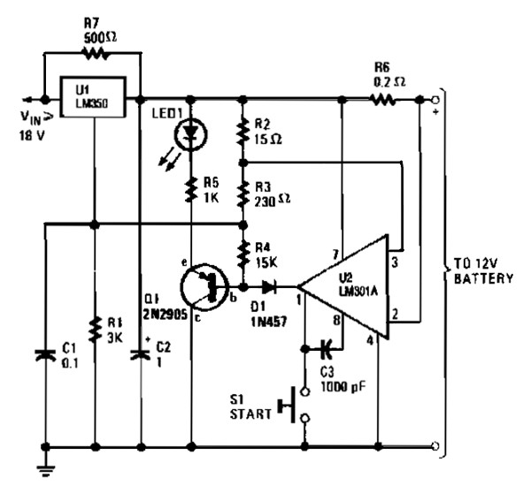
The gelled lead-acid battery charger circuit diagram enables rapid charging of gelled lead-acid batteries and automatically shuts off upon reaching full charge. Initially, the charging current is maintained at 2 A; however, as the battery voltage increases, the current...
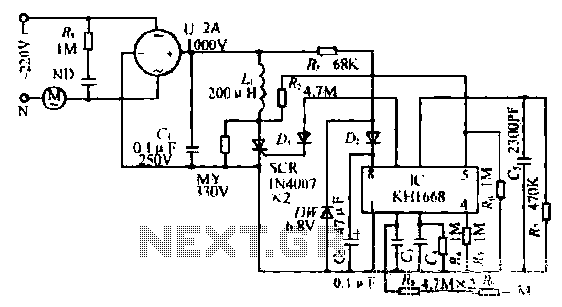
The synchronous vibration circuit operates with a control logic that includes three primary components. An internal oscillator is initiated by a synchronization pulse, transitioning to a low state immediately after the pulse. Upon power activation, the internal circuitry undergoes...
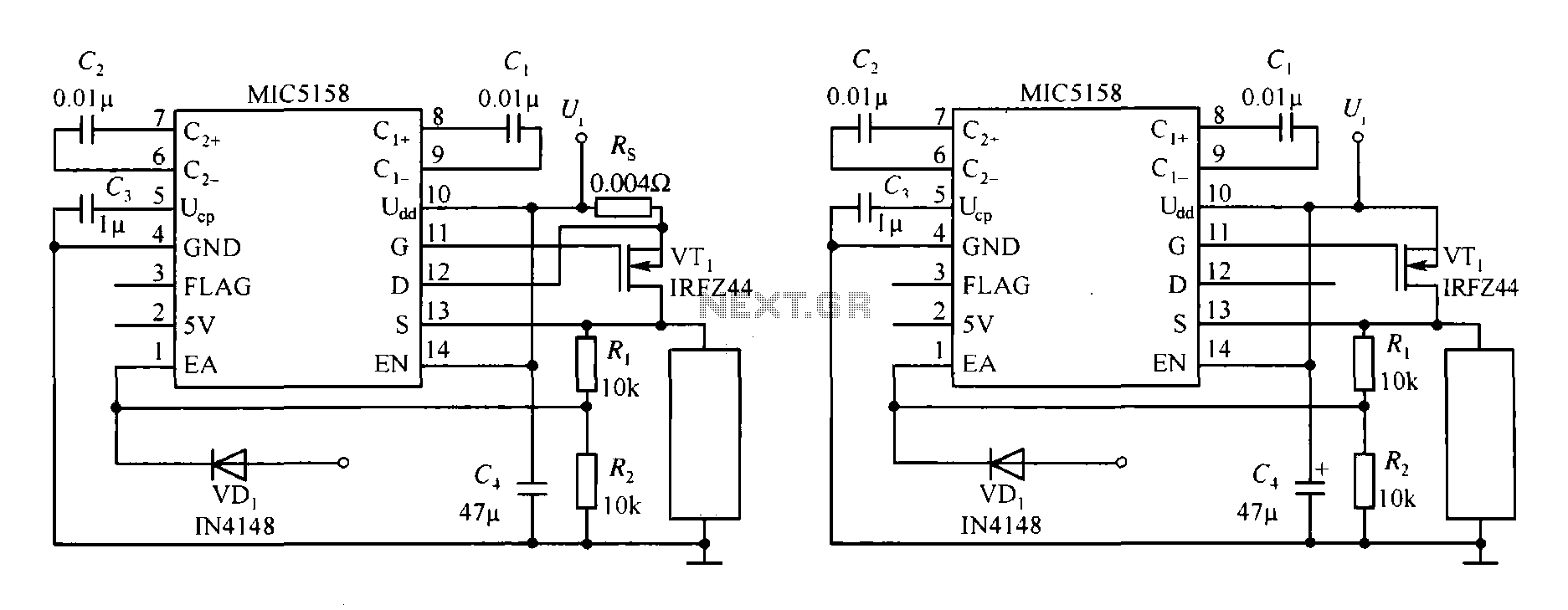
The MIC5158 is part of a high-speed switching circuit diagram that focuses on the rising edge. The MIC5158 is a precision voltage reference and high-speed switching device that is commonly utilized in various electronic applications requiring rapid signal transitions. In...
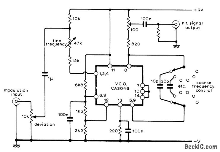
A sine-wave input can be applied to an RCA CA3046 transistor array configured as a voltage-controlled oscillator (VCO), which functions effectively as a low-distortion frequency modulation (FM) signal generator. When a sawtooth input is utilized, the same configuration operates...