
Schematic Diagram 12v battery charger circuit

The described 12V battery charger circuit functions through a combination of transistor switching and voltage feedback mechanisms to ensure safe charging of the battery. The TIP3055 serves as the main power transistor, capable of handling significant current loads up to 15A, making it suitable for charging applications. The circuit's design incorporates a current limiting feature that prevents damage to the battery by ceasing operation when either the voltage exceeds 14V or the current surpasses 2A.
The BC557 and BC547 transistors are configured as a feedback control mechanism. The BC557 is a PNP transistor that activates when the voltage across the voltage divider reaches a threshold, turning on to signal the TIP3055 to stop charging. The voltage divider, formed by the 1.8kΩ and 39kΩ resistors, plays a critical role in setting this threshold. As the battery charges and its voltage rises, the voltage at the divider increases, eventually reaching 0.65V. This triggers the BC557, which in turn influences the TIP3055 to shut off, thus protecting the battery from overcharging.
In the initial state, the circuit is fully operational, with the BD139 transistor driving the TIP3055 to allow current to flow into the battery. The BD139 is an NPN transistor that ensures that the TIP3055 remains on until the feedback from the BC557 indicates that the battery is sufficiently charged. The overall simplicity of the circuit, with its reliance on just a few transistors and resistors, makes it an effective solution for charging 12V batteries in various applications, including automotive and renewable energy systems.
In summary, this battery charger circuit exemplifies a straightforward yet effective design that utilizes transistor switching to manage battery charging safely and efficiently. The careful selection of components and their arrangement allows for reliable operation while minimizing the risk of overcharging, thus extending the lifespan of the battery being charged.A very simple 12v battery charger circuit can be designed using a TIP3055 power transistor to limit the current to the battery by turning off when the battery voltage reaches approx 14v or if the current rises above 2 amp. This battery charger electronic circuit is very simple and require few external electronic parts. Signal to turn off the TIP3 055 transistor comes from two other transistors, the BC557 and BC 547. Firstly, the circuit turns on fully via the BD139 and TIP3055. The BC557 and BC 547 do not come into operation at the moment. As the battery voltage rises, the voltage divider made up of the 1k8 and 39k creates a 0. 65v between base and emitter of the BC557 and it starts to turn on at approx 14v. 🔗 External reference
Related Circuits
The clock circuit above uses seven ICs and 19 LEDs to indicate binary coded decimal time. The LEDs can be arranged so that each horizontal group of 3 or 4 LEDs represents a decimal digit between 0 and 9...
This circuit is a compact +5V power supply that is beneficial for digital electronics experimentation. Inexpensive wall transformers with variable output voltage can be found at electronics shops and supermarkets. While these transformers are readily available, their voltage regulation...

Controlling the speed of a three-phase AC motor is achieved by regulating the frequency of the power supply, as the motor operates in synchronization with the line frequency. A three-phase AC motor speed controller functions as a three-phase sine...
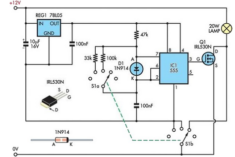
A 12V 20W halogen lamp (MR16) and a 4.2Ah SLA battery are utilized in a bike light system. Due to the limited lifespan of the battery at this power rating, a cost-effective light dimmer was designed to reduce battery...
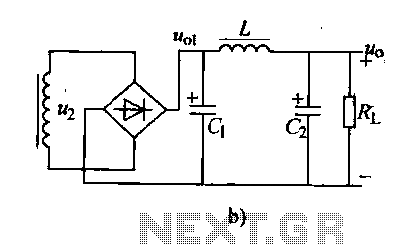
Analyzing the filter capacitance or inductance shows that the filtered DC output remains somewhat volatile. In situations requiring a smoother DC output, a duplex filter can be employed. The LC filter, which consists of a capacitor and inductor, is...

Fluorescent lamps, despite their long presence, remain enigmatic to many individuals due to their complex operational mechanisms. The lamp consists of a gas mixture, primarily containing mercury, which, when energized as an arc, produces a significant amount of short-wave...