
3 phase ac motor speed control circuit

The three-phase AC motor speed controller is implemented through a sine wave inverter, which converts the DC supply voltage into a three-phase AC output with adjustable frequency. The core of the circuit typically includes a microcontroller or a digital signal processor (DSP) that generates the required PWM (Pulse Width Modulation) signals to control the switching devices, such as MOSFETs or IGBTs, in the inverter stage. These devices are arranged in a three-phase bridge configuration to produce the necessary output waveforms.
The integrated circuit chip designed for this purpose simplifies the control of the inverter, allowing for precise frequency adjustments that directly influence motor speed. The PWM technique modulates the duty cycle of the output signals, effectively controlling the voltage applied to the motor. This modulation results in a variable frequency output, which is essential for speed control.
Optical isolation is implemented using opto-isolators to protect the low voltage control circuit from the high voltage power circuit. This is critical for ensuring operator safety and protecting sensitive components from voltage spikes or transients. The layout of the circuit must be meticulously designed, ensuring that high and low voltage traces are adequately separated to prevent interference and reduce the risk of electrical shock.
In the final design, careful consideration of component ratings, thermal management, and filtering techniques is necessary to enhance the reliability and efficiency of the motor controller. The selection of appropriate capacitors, inductors, and heat sinks will play a significant role in the overall performance and longevity of the device. Furthermore, implementing feedback mechanisms, such as current sensing and speed feedback loops, can improve the control accuracy and responsiveness of the motor speed controller.Controlling the speed of three phase ac motor is done by controlling the frequency of the power line supply, since the motor is synchronized with the line frequency. Three phase ac motor speed controller is actually nothing more than three phase sine wave power inverter with variable frequency.
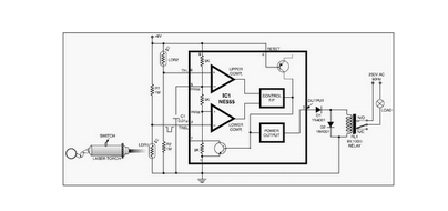
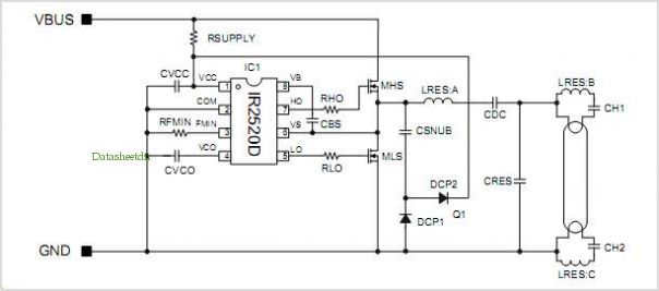
The three phase power inverter is a complex circuit, but fortunately there is an integrated circuit chip for this purpose. This is the figure of the circuit; For the final motor driver circuit, you can see the component values are shown only for OB2 channel, but the others are similar. This 3 phase ac motor controller use optical isolation, so you must be careful in designing the layout, to make a clear separation between low and high voltage network.
This separation is useful for minimizing the risk of hazardouz electrical shock. 🔗 External reference
Related Circuits
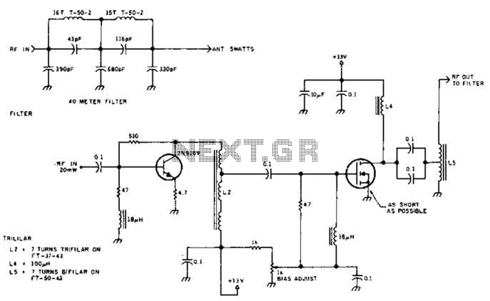
The circuit illustrated is designed to generate up to 5 watts of RF output in the 40-meter (7 MHz) amateur band. The coils depicted are wound on toroidal cores from Armdon Associates Inc., with part numbers provided in the...
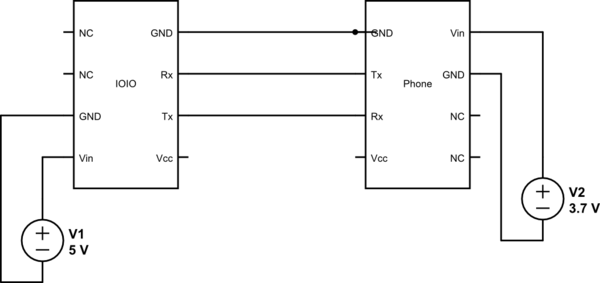
This project utilizes Sparkfun's IOIO for Android, focusing on power consumption concerns. The IOIO board can provide the phone with 500 mA charging, which may be excessive for continuous operation. The proposed solution is to power both the phone...
This circuit is designed around a 555 timer and utilizes a minimal number of components. Due to its simplicity, it can be easily constructed and operated by beginners. The circuit leverages the 555 timer IC, which is a versatile and...
The single-junction transistor is commonly utilized in sawtooth and pulse generators, and it can also be configured to create a basic sine wave generation circuit. As an oscillator circuit composed of discrete components, it requires a minimal number of...
This compressor will compress a 25-mV peak-to-peak (p-p) audio signal to a 20-V p-p output, maintaining input levels between 1.5 V p-p and 3.5 V p-p, with a frequency response ranging from 7 Hz to 67 kHz. It is...
LCD modules have become a popular means of displaying system messages and status in embedded applications. This application note demonstrates how to interface an SST FlashFlex microcontroller to a typical character LCD module. The SST FlashFlex is an industry-standard,...