
schematic of programmer radio
C0QBmk~%24(KGrHqIOKkIEq4M%2Bu,)1BK2zHH580Q~~_35.gif "of programmer radio")
The schematic of a programmer radio typically includes various components essential for its operation, such as a microcontroller, radio frequency (RF) module, power supply, and audio output circuitry. The microcontroller serves as the central processing unit, controlling the overall functionality of the radio, including tuning, volume control, and user interface.
The RF module is responsible for receiving and transmitting radio signals. It should be designed to operate within the desired frequency range and may include additional features such as frequency modulation (FM) or amplitude modulation (AM) capabilities. The power supply section is crucial, providing the necessary voltage and current to the circuit while ensuring stable operation under various conditions.
Audio output circuitry is essential for converting the electrical signals received by the RF module into audible sound. This can include amplifiers, filters, and speakers or headphone jacks. The schematic should also include necessary passive components like resistors and capacitors, which play roles in signal conditioning and power management.
Furthermore, the user interface may involve buttons, knobs, or a display, allowing users to interact with the radio. The schematic must clearly indicate the interconnections between these components, ensuring that the design is coherent and functional. Proper labeling and organization of the schematic will facilitate troubleshooting and modifications in the future.
Overall, a well-designed programmer radio schematic integrates all these elements into a cohesive system that meets the intended operational requirements.This time on we Will Share About Schematics Of Radios Schematic Of Programmer Radio Latest Info at Onmilwiki.. 🔗 External reference
Related Circuits
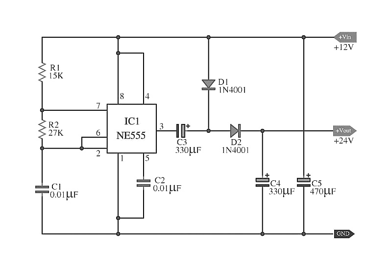
The capacitors C5 work in conjunction with IC1, while the resistors R1 and R2, along with capacitors C1, form an astable multivibrator square wave generator. This generator outputs a frequency of approximately 2 kHz from pin 3 of IC1....
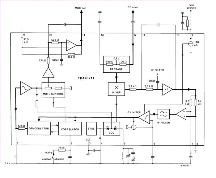
The TDA7021T integrated radio receiver circuit is designed for portable radios, both stereo and mono, where minimal peripheral components are essential for achieving small dimensions and low cost. It is fully compatible. The TDA7021T is a highly integrated radio receiver...
Approximately 20 years ago, small key-holders that emitted an intermittent beep for a few seconds upon detecting a whistle were quite common. These devices utilized a specialized integrated circuit (IC) that made them unsuitable for home construction. The current...
This indicator shows whether the phone is busy or not. When the line is busy, LED D6 is off. The line voltage at points A and B is attached. By the rectifier bridge behind the connection, the polarity does...
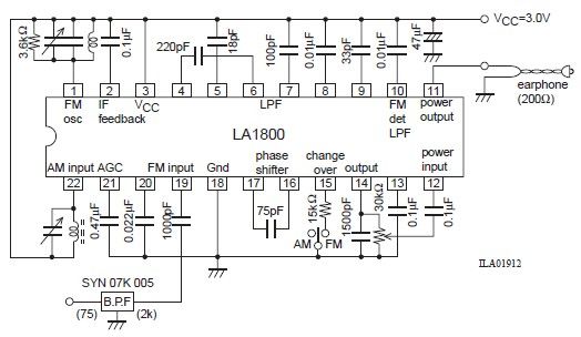
This portable AM/FM radio circuit is designed using the LA1800 integrated circuit (IC) along with several external components. The LA1800, manufactured by Sanyo Semiconductors, requires only a few additional components for its operation. The output signal is directed to...
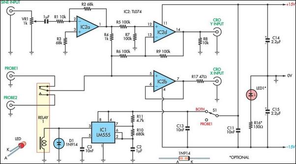
This unit utilizes a dual trace oscilloscope with X-Y functionality as a display to test and demonstrate the operation of circuits and components such as transistors, diodes, zener diodes, and both terminated and unterminated transformers. A low-frequency sine wave...