
Phone Busy Indicator schematic

The circuit described operates as a telephone line indicator, providing visual feedback on the status of a phone line. The primary component responsible for this functionality is an LED (D6) that indicates whether the phone line is busy or free.
When the phone line is busy, the voltage across the line drops, causing the LED to turn off. Conversely, when the line is free, the voltage rises to approximately 60 V, which allows the FET (T1) to conduct, thereby turning the LED on.
The circuit employs a voltage divider configuration to manage the high voltage present on the telephone line. This divider is crucial for scaling down the voltage to a safe level that can be processed by the rest of the circuit, including the FET and any associated components. The use of a rectifier bridge ensures that the circuit can handle the AC voltage from the telephone line without being affected by polarity, making it versatile for different types of connections.
A zener diode and capacitor are included in the design to stabilize the voltage and protect the circuit from voltage spikes that may occur on the line. It is important that these components are correctly oriented to ensure proper operation.
The circuit is designed to be powered by a 9 V battery, which is suitable for driving the LED at a current of approximately 10 mA. This current level is adequate for ensuring that the LED is sufficiently bright for visibility while maintaining a low power consumption from the battery.
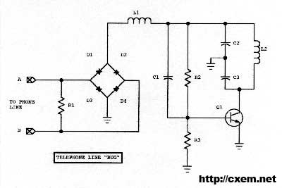
Overall, this circuit provides a simple yet effective means of indicating the status of a telephone line, utilizing common electronic components to achieve reliable performance.This indicator shows whether the phone is busy or not. When the line is busy, LED D6 off. The line voltage at points A and B attached. By the rectifier bridge behind the connection, the polarity does not matter. The voltage of 60 V is the voltage divider. The voltage at the voltage divider to the negative mass (capacitor and zener diode are not incorrectly signed). When the line is not busy, the line is approximately 60 V. The FET T1 will conduct and the LED lights up. Is the phone listed, then drops the voltage and the FET is not conducting and the LED goes out. When connecting to the telephone line that is approximately 60 V, which is not really low-voltage can be expected. The circuit is best with a 9 V battery powered. If the LED is running a current of 10 mA. 🔗 External reference
Related Circuits
Wireless Telephone Bug. This project enables monitoring of a phone line as soon as the phone is off-hook. A regular FM broadcast band radio can be utilized for this purpose. The Wireless Telephone Bug is a circuit designed to allow...
With this circuit mounted in or near every phone in the house, it will allow users to know if the phone is being used and not to pick up the phone. When a phone is taken off hook, the...
This circuit diagram represents a resource replacement for 1.3V mercury cells or other small batteries. It has various applications, including use in computers to activate a front panel multi-adapter equipped with a digital thermometer. The circuit draws power from...
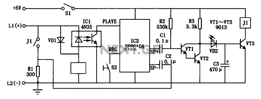
An automatic telephone responder circuit is illustrated. It incorporates a 10-second voice recording circuit (SR9G10A) activated by the power switch (S2). The circuit utilizes an electret microphone (IC2) for sound input. To initiate the response, the user must press...
The general principle is that reading prepares an individual, writing fosters daily improvement, and practice leads to perfection. Merely having theoretical knowledge is insufficient for an Electronics and Communication Engineering (ECE) student. A project entails developing hardware alongside software,...
The computer needs at least 180 millivolts peak-to-peak and the condenser microphone in my headset produces about 20 millivolts peak-to-peak into a 2.2k load with normal speech levels. There are USB ports on the machines, so I can use...