
Schematics 100W Power Amplifier for Guitar

The provided schematic outlines a pre-amplifier and power amplifier circuit specifically designed for electric guitar applications. The pre-amplifier stage is responsible for boosting the weak signal from the guitar's pickups to a level suitable for further amplification. It typically employs operational amplifiers (op-amps) configured in a non-inverting arrangement to achieve high input impedance and low output impedance, ensuring minimal signal loss and distortion.
The power amplifier stage follows, designed to drive the speaker with sufficient power to produce audible sound levels. This stage may utilize a Class A, Class B, or Class AB configuration, depending on the desired sound characteristics and efficiency. The power amplifier is crucial for delivering the necessary wattage to the speaker while maintaining fidelity to the original guitar signal.
The schematic will also include details on component selection, such as resistor and capacitor values, which are critical for setting gain levels and frequency response. Additionally, it may provide information on power supply requirements, including voltage ratings and current capacities necessary for optimal performance.
Instructions for constructing the enclosure will likely cover materials, dimensions, and assembly techniques to ensure durability and aesthetic appeal. Proper grounding and shielding techniques will also be emphasized to minimize noise and interference, which are particularly important in guitar amplifiers.
Overall, this schematic serves as a valuable resource for both novice and experienced builders seeking to create a high-quality guitar amplification system.You need this schematics. Go to THIS page and you will find a good pre-amp and power amplifier for your guitar include the complete explanation of its works, and how to build the box. 🔗 External reference
Related Circuits
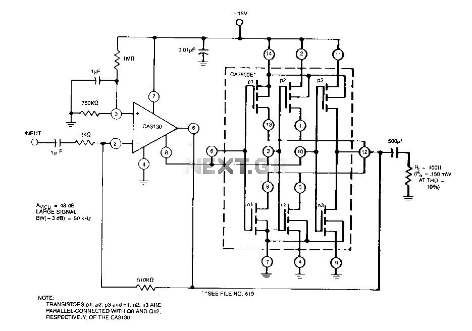
This circuit effectively enhances the current-sourcing and current-sinking capabilities of the CA3130 BiMOS operational amplifier. This configuration increases the current-handling capacity of the CA3130 output stage by approximately 2.5 times. The circuit described is designed to augment the output performance...
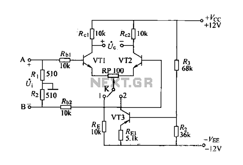
The differential amplifier is known for its stability and zero drift suppression. The circuit, as illustrated, utilizes two identical transistors, VT1 and VT2 (both 3DG6). The reference values for the component parameters are depicted in the figure. The circuit...
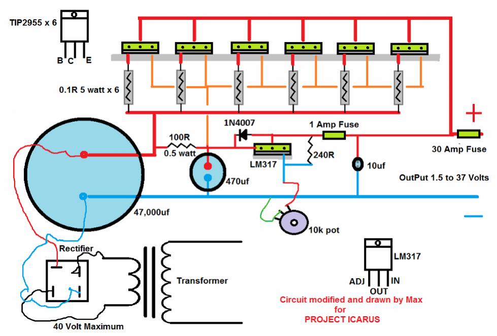
A DC-DC power supply schematic is required that outputs a voltage between 12.7V and 14.5VDC, with an input voltage range from 12VDC upwards. The design of a DC-DC power supply capable of outputting a regulated voltage between 12.7V and 14.5VDC...
This circuit is a small +5V power supply, which is useful when experimenting with digital electronics. Small inexpensive wall transformers with variable output voltage are available from any electronics shop and supermarket. Those transformers are easily available, but usually...

This circuit features a high-input-impedance AC resistance of 880 kΩ and a gain of 10, utilizing an operational amplifier for a piezoelectric transducer. The described circuit is designed to interface with a piezoelectric transducer, which generates an AC voltage in...
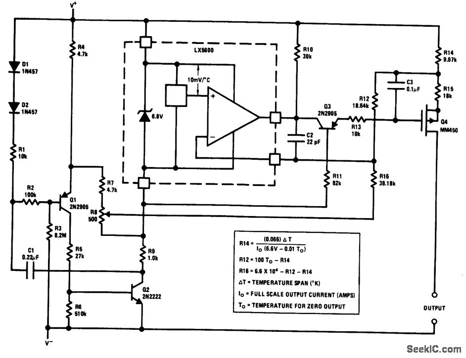
The output of this circuit is a current that is proportional to temperature, which can be utilized to drive a meter for direct readout. Alternatively, a resistor or operational amplifier can be employed to obtain a voltage output. The...