
Schematics

A graphical representation of a system serves as a crucial tool in the field of electronics, particularly when illustrating the functionality and interconnections of various components within electronic circuits. This representation is commonly found in printed circuit boards (PCBs) and integrated circuits (ICs), where it provides a visual guide for understanding the arrangement and operation of electronic elements.
In the context of PCBs, the graphical representation includes symbols for resistors, capacitors, transistors, and other components, interconnected by lines that denote electrical connections. This schematic diagram enables engineers to visualize how signals flow through the circuit, facilitating troubleshooting, design modifications, and communication among team members during the development process.
For integrated circuits, the graphical representation may take the form of a layout diagram that details the physical placement of components on the silicon chip. This layout is critical for ensuring optimal performance, as it affects factors like signal integrity, power distribution, and thermal management. The representation may also include logic gates, which are fundamental building blocks in digital circuits, and Hardware Description Languages (HDL) that define the behavior and structure of electronic systems at a higher level.
Overall, the graphical representation of a system is an essential aspect of electronic design, providing clarity and insight into the complex interactions of components that underpin modern electronic devices.A graphical representation of a system. It often refers to electronic circuits on a printed circuit board or in an integrated circuit (chip). See logic gate and HDL. 🔗 External reference
Related Circuits
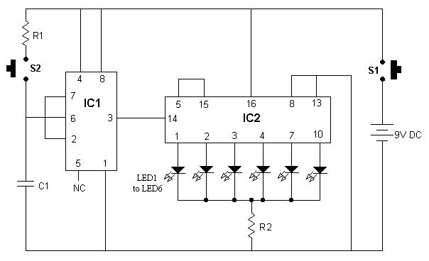
It is advisable to enclose this circuit in a box and label each LED with numbers from 1 to 6. When switch S1 is momentarily pressed, one of the six LEDs will illuminate, with the number corresponding to the...
This document contains a collection of various useful and interesting electronic schematics. Some of these schematics are referenced or included in other documents on this site. Notably absent from this collection is extremely important safety information, which can be...
The circuit is divided into two sections: the isolated external loop connected to the remote interface connector on the front of the power supply unit (PSU) and the non-isolated inner loop connected to the high-tension (AC line) supply. The...
The two circuits below illustrate generating low frequency sinewaves by shifting the phase of the signal through an RC network so that oscillation occurs where the total phase shift is 360 degrees. The transistor circuit on the right produces...
This document presents plans for a simple ground plane antenna that is effective in the FM band (88-108 MHz). It is constructed from a small plastic disk. The 6 x 6 loop antenna, designed by Graham Maynard, is highlighted...
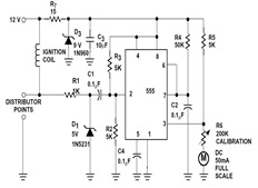
The sections available in this datasheet cover general design considerations for the 555 timer, frequently asked application questions (FAQ), design formulas, and examples of innovative applications. Examples of applications include a Missing Pulse Detector, Pulse Width Modulation (PWM), Tone...