
Sinewave Generator schematics

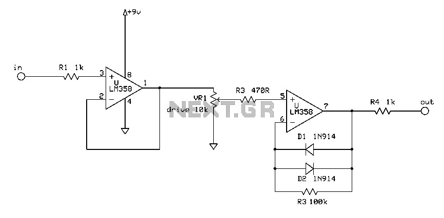
More: The op-amp based phase shift oscillator is much more stable than the single transistor version since the gain can be set higher than needed to sustain oscillation and the output is taken from the RC network which filters out most of the harmonic distortion. The sinewave output from the RC network is buffered and the amplitude restored by the second (top) op-amp which has gain of around 28dB. Frequency is around 600 Hz for RC values shown (7.5K and 0.1uF) and can be reduced by proportionally increasing the network resistors (7.5K). The 7.5K value at pin 2 of the op-amp controls the oscillator circuit gain and is selected so that the output at pin 1 is slightly clipped at the positive and negative peaks. The sinewave output at pin 7 is about 5 volts p-p using a 12 volt supply and appears very clean on a scope since the RC network filters out most all distortion occurring at pin 1.
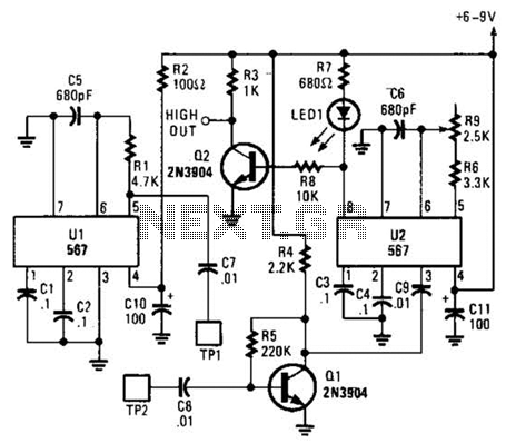
The described circuits implement methods for generating low-frequency sine waves using phase shift techniques. The first circuit utilizes a transistor, specifically a 3904 NPN transistor, configured in a phase shift oscillator arrangement. The oscillator relies on an RC network that achieves a total phase shift of 360 degrees, allowing for sustained oscillation. The output from the collector of the transistor is buffered by a JFET, providing a low impedance output suitable for driving subsequent stages. The gain of this circuit is crucial; it must be finely tuned by adjusting a 500-ohm resistor to minimize distortion and stabilize the waveform. However, due to the sensitivity of the gain adjustment, this configuration is not ideal for practical applications.
In contrast, the op-amp based phase shift oscillator presents a more stable alternative. This circuit employs operational amplifiers to create a feedback loop that sustains oscillation with a higher gain than necessary, thus enhancing stability. The output is derived from the RC network, which effectively filters out harmonic distortion, resulting in a cleaner sine wave. The configuration uses a resistor of 7.5K ohms and a capacitor of 0.1 µF, yielding an oscillation frequency of approximately 600 Hz. The gain of the second op-amp is set to around 28 dB, allowing the output to be restored to the desired amplitude. The resistor at pin 2 of the op-amp is critical for controlling the oscillator gain, selected to ensure that the output at pin 1 is slightly clipped at both peaks. With a 12-volt supply, the sine wave output at pin 7 measures about 5 volts peak-to-peak, exhibiting a clean waveform on an oscilloscope, thanks to the effective filtering characteristics of the RC network. Overall, the op-amp circuit offers a more robust solution for generating low-frequency sine waves compared to the transistor-based approach.The two circuits below illustrate generating low frequency sinewaves by shifting the phase of the signal through an RC network so that oscillation occurs where the total phase shift is 360 degrees. The transistor circuit on the right produces a reasonable sinewave at the collector of the 3904 which is buffered by the JFET to yield a low impedance output.
The circuit gain is critical for low distortion and you may need to adjust the 500 ohm resistor to achieve a stable waveform with minimum distortion. The transistor circuit is not recommended for practical applications due to the critical adjustments needed.
The op-amp based phase shift oscillator is much more stable than the single transistor version since the gain can be set higher than needed to sustain oscillation and the output is taken from the RC network which filters out most of the harmonic distortion. The sinewave output from the RC network is buffered and the amplitude restored by the second (top) op-amp which has gain of around 28dB.
Frequency is around 600 Hz for RC values shown (7.5K and 0.1uF) and can be reduced by proportionally increasing the network resistors (7.5K). The 7.5K value at pin 2 of the op-amp controls the oscillator circuit gain and is selected so that the output at pin 1 is slightly clipped at the positive and negative peaks.
The sinewave output at pin 7 is about 5 volts p-p using a 12 volt supply and appears very clean on a scope since the RC network filters out most all distortion occurring at pin 1. 🔗 External reference
Related Circuits
Integrated circuit gates IC1-a and IC1-b form a monostable multivibrator, whose time constant is determined by capacitor C2 and resistor R3. When the transmitter is dekeyed and then almost immediately rekeyed, point TX+ goes low, causing pin 1 to...
This circuit is a resonant twin-T filter. Its purpose is to provide a reasonable imitation of a low-pass response, which it achieves effectively. The schematic illustrates two variations: one with self-oscillation and one without. The version built includes oscillation....
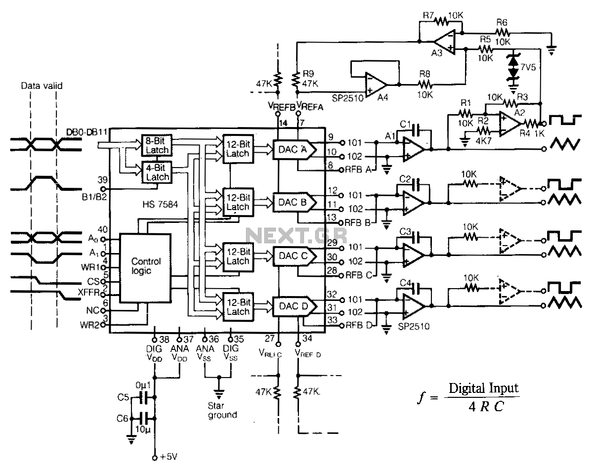
The programmable multiple output generator provides control signals for the data converter automated test equipment (ATE). Major performance criteria include simple interfaces with various microprocessor systems, low power consumption, stable output timing relationships, and minimal board space requirements. For...
This circuit should only be attempted by individuals with a strong understanding of electronic devices. It is connected to a main power source (220V) and poses a risk of high electrical shock. This circuit operates at a mains voltage of...
The integrated circuit (IC) generates various sound effects, with the output at Pin 3 amplified by a transistor. A 64-ohm loudspeaker can replace the 56-ohm resistor and 8-ohm loudspeaker. A two-pole, four-way switch controls the sound effects, with position...
This bell ring generator utilizes the MC14106 or 40106 hex Schmitt inverter IC to produce a dual-tone ringing sound akin to that of standard doorbell units. The circuit design of the bell ring generator is centered around the MC14106 or...