
Schmitt trigger light

The circuit design leverages the 555 timer's ability to operate as a Schmitt trigger, providing hysteresis that stabilizes the output in the presence of fluctuating light conditions. The photosensitive resistor (RG) is a critical component that responds to varying light levels, with its resistance decreasing as light intensity increases. This behavior allows the circuit to respond dynamically to changes in ambient lighting.
In this configuration, the 555 timer is powered by a voltage supply (VDD). The two comparators are set to trigger at different voltage levels—1/3 VDD and 2/3 VDD—enabling the circuit to maintain a stable output state despite minor variations in light intensity. The output pin (K) is connected to an external load, which may be an LED or another device that requires activation based on light levels.
The circuit's operation can be summarized as follows: Under bright light conditions, RG's resistance decreases, causing pin 2 of the 555 timer to register a low voltage, thus setting the output low and keeping the connected load in an off state. As the light diminishes, RG's resistance increases, leading to a voltage rise at pin 6. Once this voltage exceeds the 2/3 VDD threshold, the timer resets, and the output pin (K) transitions to a high state, activating the load. This functionality allows the circuit to serve as an effective light-sensitive switch, responding appropriately to changes in environmental light. As shown, the circuit 555 as the core, and the composition of the photosensitive resistor RG and RP1 like. RG strength with light exhibit different resistance, reset and set th e internal feature uses two comparators 555, and may form a Schmitt trigger. When the light intensity, RG showed low resistance, 2 feet was low ( 1/3 VDD trigger level), 555 set, K does not operate; when the light is weak, RG showed a high impedance, 6 feet high level 2/3 VDD to the threshold level, the reset 555, K pull.
Related Circuits
This article is relevant only to readers whose bicycle lights are powered by a dynamo. The regulations regarding bicycle lights in the United Kingdom are stricter than in other countries, making the use of a dynamo uncommon in this...
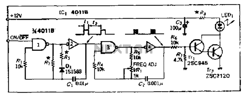
The 4000 Series 4011B is a NAND gate used in conjunction with a 4AI NAND gate circuit group to create two loops of an unstable multivibrator. The first NAND gate and the second NAND gate operate at approximately 1...
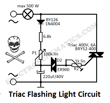
This flashing light circuit utilizes triacs to produce an intermittent light with variable frequency. Additional components include the D1 diode and a semi-adjustable resistor. The flashing light circuit is designed to create a visual indication through intermittent illumination, which can...
A compact and intriguing circuit designed to flash automotive headlights. The circuit diagram is based on the well-known NE555 timer circuit. This circuit utilizes the NE555 timer in astable mode to create a flashing effect for automotive headlights. The primary...
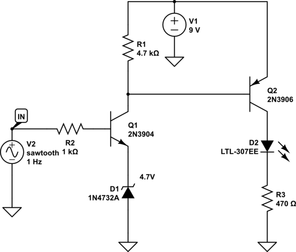
A LED is used to indicate when a DC voltage reaches 5 volts or more. The LED should be fully illuminated at 5 volts and not dim at 4.5 volts or lower. The circuit should be constructed using discrete...
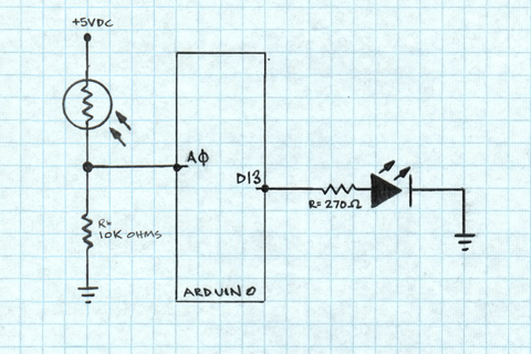
A project is underway to determine the number of sun hours available at a specific location and to track this data over time as part of solar power installation design. The concept involves utilizing a light detector exposed to...