
Headlight Flashers

This circuit utilizes the NE555 timer in astable mode to create a flashing effect for automotive headlights. The primary components include the NE555 timer IC, resistors, capacitors, and a power supply, typically sourced from the vehicle's battery.
In the astable configuration, the NE555 continuously switches between its high and low states, generating a square wave output. This output is used to control a relay or a transistor that, in turn, switches the headlights on and off at a predetermined frequency. The flashing rate can be adjusted by varying the resistor and capacitor values connected to the timer.
For instance, using a larger capacitor or increasing the resistance in the timing circuit will slow down the flashing rate, while smaller values will increase the frequency. The circuit can be powered directly from the vehicle's 12V battery, making it suitable for automotive applications.
Additional components may include diodes for protection against back EMF generated by the relay, ensuring the longevity of the circuit. Proper heat dissipation measures should also be considered if the circuit is expected to operate for extended periods.
This flashing headlight circuit can enhance vehicle visibility and serve as a signaling device, contributing to road safety. The simplicity of the NE555 timer circuit makes it an ideal choice for both novice and experienced electronics enthusiasts looking to implement a practical automotive application.Small and interesting circuit that flashes your head lights. Automotive, head lights, circuit diagram. Built around famous NE555 timer circuit.. 🔗 External reference
Related Circuits
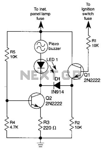
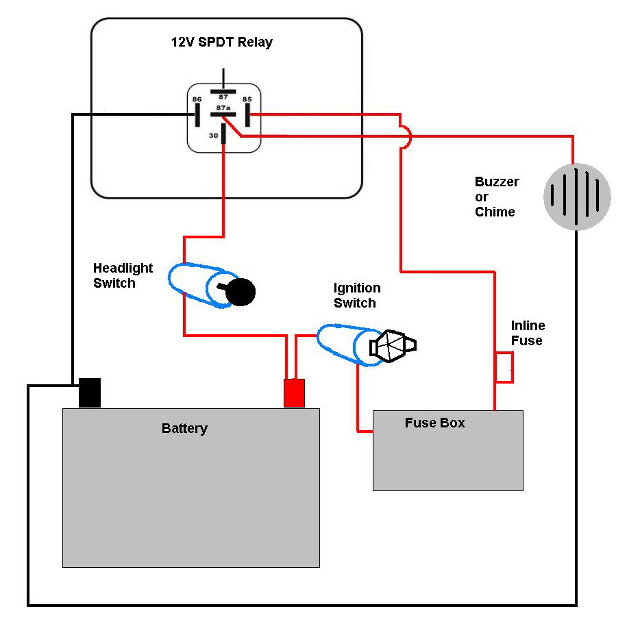
The base of Q1 is connected to the car's ignition circuit; the easiest point to make that connection is at the ignition switch fuse in the car's fuse panel. Also, one side of the piezoelectric buzzer is connected to...
Motor Bike Headlight Controller Circuit. This circuit automatically turns a motorcycle's headlight on and off, independently of both the light and ignition switches, provided the battery is fully charged. The first stage... The motorcycle headlight controller circuit is designed to...
There is a need for improved headlights. Research has been conducted, including participation in ongoing forum discussions; however, basic information is still required. To enhance the performance of vehicle headlights, several factors must be considered, including the type of bulbs...
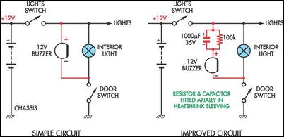
Two headlight reminder circuits are designed for easy installation and operation based on the KISS (Keep It Simple Stupid) principle. The basic circuit consists of a 12V piezo buzzer connected between the lights circuit and a door switch. The...
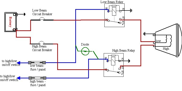
A bike equipped with a 35-watt HS1 bulb is being upgraded to a brighter headlight using an H4 60/65-watt xenon bulb. An expert recommended using relays due to the increased power requirements of the new bulb. Research conducted on...
This circuit must be connected to a 5 volt DC source. See my RR page for several 5 volt supplies. Note the flashing LED is optional, but looks so good on the top of a locomotive. The circuit described is...