
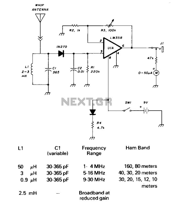
Schottky Field Strength Meter

A stereo headphone jack provides a way to connect the amplified detector output to a digital voltmeter, chart recorder, oscilloscope, or other instruments, and also allows the application of an offset voltage from an external device. An offset knob allows correction for drift in the Schottky detector as well as offsets created by interfering signals. A coarse offset control on the circuit board allows for compensation for the mismatch between components.
A power switch and pilot light complete the set of user controls. The Schottky diode detector is built on a single-sided fiberglass circuit board that is separate from the amplifier board. This was mainly because the detector board needed to be close to the RCA input connector, which would be on the front panel. With the presence of the other connector and the controls on the front panel, there was no room for a larger circuit board to accommodate the DC amplifier.
Whip antennas require a ground structure in order to work. The large copper areas on the detector board are intended to improve the efficiency of a short whip antenna at GHz frequencies. Being in a mostly unshielded enclosure, the meter can detect strong GHz range signals picked up on its internal leads, without the need for an external antenna. The signal from the detector, which can be treated as DC, is buffered by voltage follower U1A. R9 is intended to compensate for input bias drift in U1A, and C6 is intended to assure that there would not be excessive lag in the feedback through R9 because of stray capacitance and the input capacitance of U1A's inverting input.
The second stage is the adjustable gain stage, U1B. With the component values shown in the schematic, this amplifier has a gain that ranges from 1X to 148X. The use of an 87k potentiometer provides an actual gain range of 1X to 137X. This meter is not calibrated, so parts tolerance is not much of an issue.
The output of this stage is applied to the meter driver and to the stereo headphone jack. When the meter is properly zeroed, the voltage at this point will go negative with respect to ground. The meter driver serves two purposes: it limits the maximum amount of current that can pass through the meter movement, and putting the meter movement in the feedback path of an inverting amplifier, instead of to ground, assures that the current to drive the meter movement flows from the battery terminals through the amplifier stages and not through the artificially generated ground. Keeping the meter movement current out of the ground circuit minimizes the chance of incidental feedback through the grounds that could result in oscillation.
Advantages of using a printed circuit board for the detector over using other construction methods include the ability to use surface mount parts, which provide small physical dimensions that minimize parasitic reactances, and good thermal coupling of both diodes to the circuit board. Keeping the diodes at the same temperature is important in minimizing temperature-caused drift. The meter operates from the power of two AA cells. With new Zinc Chloride cells installed, it draws only about 3 milliamps, including the LED when the meter reads full scale, and about 3.5 milliamps when the meter reads zero, indicating that the use of an external power supply would not be worthwhile.When an antenna is attached, (or even if not, in the presence of a strong RF field) the field strength meter has a moving coil meter to indicate relative field strength. The box holds a Schottky diode detector, a DC amplifier, and a meter display. If the parts used in construction are the same values shown in the schematic, the meter shows full scale ("+3db" on the surplus store VU meter movement) when the output of the Schottky diode detector is between 1.6 millivolts and 160 millivolts, depending up the setting of the gain control.
Since opamps are used as amplifiers, the range of the gain control can be modified easily. The actual sensitivity in terms of field strength is primarily a function of the antenna system, and that is well beyond the scope of this web page. An RCA connector with which you can attach an antenna (as in the photograph near the top of the page), of if desired signal preconditioning circuits such as a filter and/or preamp. I expect that for most of my low power uses, a short whip antenna or no antenna at all will be sufficient.
A stereo headphone jack that provides a way to connect the amplified detector output to a digital voltmeter, chart recorder, oscilloscope, or other instrument, and also allows the application of an offset voltage from an external device. I had imagined adding an external logger with an automatic offset adjust function. An offset knob allows correction for drift in the Schottky detector as well as offsets created by interfering signals.
A coarse offset control on the circuit board allows for compensation for the mismatch between components. A power switch and pilot light complete the set of user controls. The Schottky diode detector is built on a single sided fiberglass circuit board that is separate from the amplifier board.
This was mainly because the detector board needed to be close to the RCA input connector, which would be on the front panel. With the presence of the other connector and the controls on the front panel, there was no room for a larger circuit board to accommodate the DC amplifier.
Whip antennae require a ground structure in order to work. The large copper areas on the detector board, as show in the picture above, are intended to improve the efficiency of a short whip antenna at GHz frequencies. Being in a mostly unshielded enclosure, the meter can detect strong GHz range signals picked up on its internal leads, without the need for an external antenna.
The signal from the detector, which we can treat as DC, is buffered by voltage follower U1A. R9 is intended to compensate for input bias drift in U1A and C6 is intended to assure that there would not be excessive lag in the feedback through R9 because of stray capacitance and the input capacitance of U1A's inverting input. Upon reviewing the schematic, I see that if I had a resistor closer to 1.5 Meg Ohms, it would have provided a better approximation of the input resistance seen by the noninverting input of U1A.
C6, The capacitor across R9 is a low leakage polypropylene type. The second stage is the adjustable gain stage, U1B. With the component values shown in the schematic, this amplifier has a gain that ranges from 1X to 148X. I went through my collection of surplus store 100k pots and found that they measured between 60k and 87k, so I used the 87k pot, which gave me an actual gain range of 1X to 137X.
This meter is not calibrated, so parts tolerance is not much an issue. The output of this stage is applied to the meter driver and to the stereo headphone jack. When the meter is properly zeroed, the voltage at this point will go negative with respect to ground. The meter driver serves two purposes - it limits the maximum amount of current that can pass through the meter movement, and putting the meter movement in the feedback path of an inverting amplifier, instead of to ground, assures that the current to drive the meter movement flows from the battery terminals through the amplifier stages and not through the artificially generated ground.
Keeping the meter movement current out of the ground circuit minimizes the chance of incidental feedback through the grounds that could result in oscillation. Advantages of using a printed circuit board for the detector over using other construction methods, are that it allows the use of surface mount parts, which not only provides for small physical dimensions which minimize parasitic reactances, but also provide for good thermal coupling of both of the diodes to the circuit board.
Keeping the diodes at the same temperature is important in keeping temperature caused drift as small as possible. The meter operates from the power of two AA cells. With new Zinc Chloride cells installed, it draws only about 3 milliamps, including the LED when the meter reads full scale, and about 3.5 milliamps when the meter reads zero, so it seems that the use of an external power supply would not be worthwhile.
🔗 External reference
Related Circuits
CI and LI resonate on the 1750-meter band, with coverage from 150 kHz to 500 kHz. LI can be slug-tuned for 160 to 190 kHz coverage alone, or a 2.5 mH choke can be used for LI, if desired,...
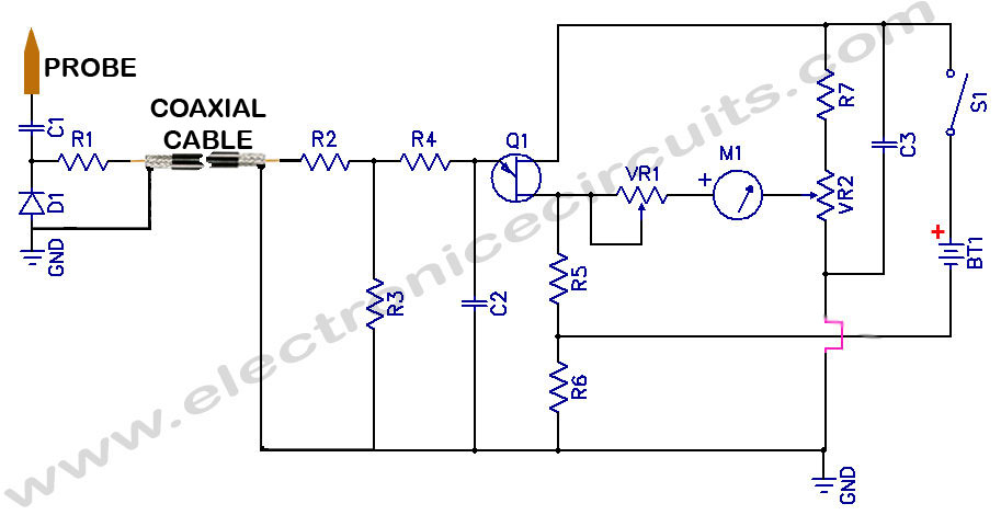
Sensitive RF Voltmeter Probe Circuit. This circuit measures RF voltages beyond 200 MHz and up to approximately 5V. The sensitive RF voltmeter probe circuit is designed to accurately measure radio frequency (RF) voltages in the range exceeding 200 MHz,...
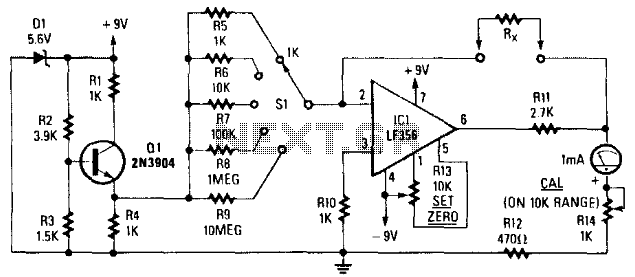
Rx is placed in the feedback path of IC1. A known reference current is chosen from the reference voltage generator Q1, D1, and resistors R5 through R9. A meter reading will be displayed, where R^ represents Rs through R9,...
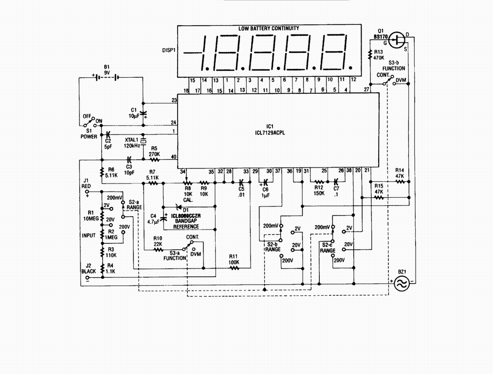
Single-chip digital voltmeter. This 4 1/2-digit DVM circuit is built around a Maxim ICL7129ACPL A/D converter and LCD driver. An ICL8069 CCZR 1.2-V band-gap reference diode is used for accuracy. The described circuit is a single-chip digital voltmeter (DVM) utilizing...
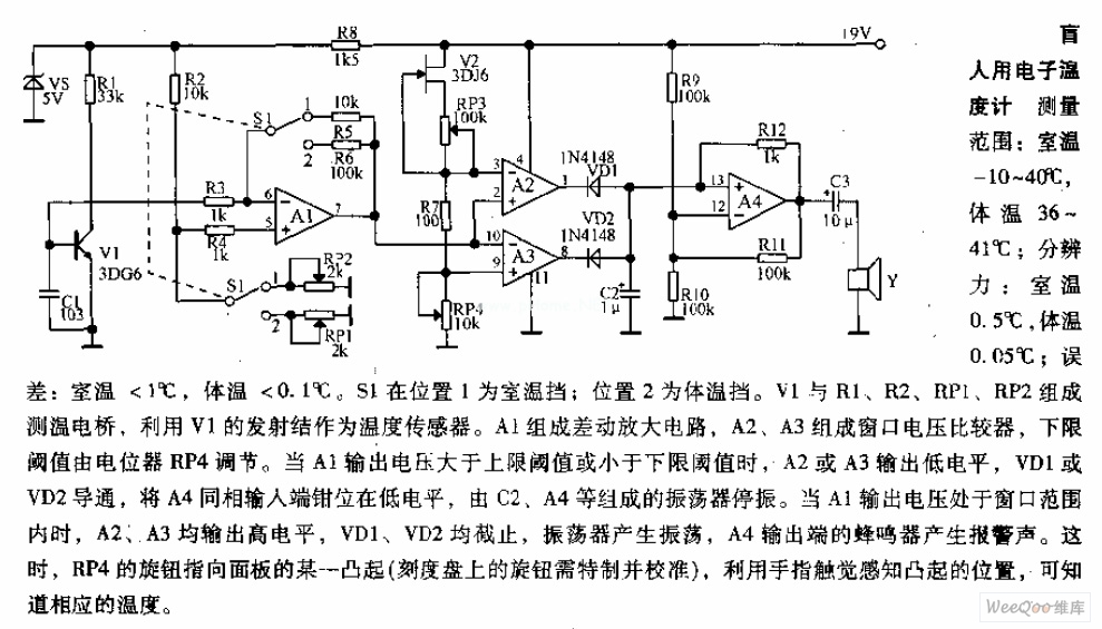
Measuring range: room temperature is -10 to 40 degrees Celsius; body temperature is 36 to 41 degrees Celsius; Resolution: room temperature is 0.5 degrees Celsius, body temperature is 0.05 degrees Celsius; error: room temperature <1 degree Celsius, body temperature <0.1 degrees Celsius. When switch S1 is in position 1, it displays the room temperature profile; position 2 displays the body temperature profile. Components V1, R1, R2, RP1, and RP2 form the temperature measurement circuit. The temperature measurement circuit is designed to monitor and display two distinct temperature ranges: ambient room temperature and body temperature. The circuit operates with a measuring range for room temperature from -10 to 40 degrees Celsius and for body temperature from 36 to 41 degrees Celsius. The resolution of the circuit is fine-tuned to provide accurate readings, with a room temperature resolution of 0.5 degrees Celsius and a body temperature resolution of 0.05 degrees Celsius. The specified error margins indicate a maximum deviation of less than 1 degree Celsius for room temperature measurements and less than 0.1 degrees Celsius for body temperature measurements. The circuit utilizes a switch, S1, which allows the user to select between the two temperature profiles. In position 1, the circuit outputs the room temperature, while in position 2, it outputs the body temperature. The operational components include a voltage source (V1), resistors (R1, R2), and potentiometers (RP1, RP2) that are integral to the measurement process. Resistors R1 and R2 are likely part of a voltage divider network that aids in scaling the temperature sensor output to a readable format. Potentiometers RP1 and RP2 can be used for calibration purposes, allowing fine adjustments to ensure that the readings are accurate within the specified error margins. The temperature sensor, which is not explicitly mentioned but is assumed to be part of the circuit, converts temperature changes into an electrical signal that can be processed by the circuit. The output from the sensor is conditioned by the resistive components to produce a voltage level that corresponds directly to the measured temperature. This voltage is then displayed on an appropriate display unit, which could be an analog gauge or a digital readout, depending on the design of the circuit. Overall, this temperature measurement circuit is a practical solution for monitoring both ambient and body temperatures with high accuracy and user-friendly operation through the selection switch.
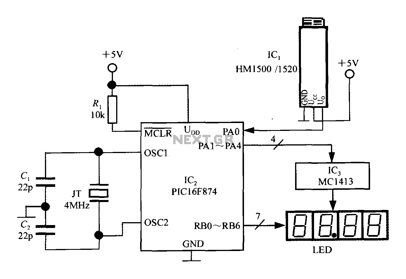
An intelligent humidity meter circuit utilizing the HM1500/1520 humidity sensor and a microcontroller configuration. The circuit operates on a +5V power supply and incorporates four common cathode LED digital displays. It employs three integrated circuits: IC1 is the HM1500/1520...