
SD card IO

The described circuit involves an Arduino microcontroller interfacing with an SD card to create a web server that can handle both input and output operations. The system utilizes analog inputs, such as sensors or potentiometers, and digital inputs from switches, which are monitored by the Arduino. The status of these inputs is then displayed on a web page, allowing users to view real-time data.
For output control, the circuit includes LEDs that can be turned on or off via commands sent from the web interface. This interaction is facilitated through the use of Ajax, which allows for asynchronous communication between the web page and the Arduino server. This technology ensures that the web page updates without the need to refresh, providing a seamless user experience.
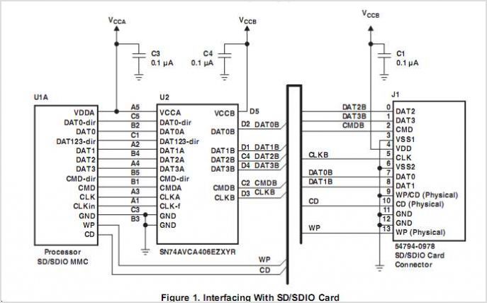
The Arduino is connected to the SD card module, which stores the HTML and JavaScript files necessary for the web interface. The SD card module is typically connected to the Arduino using the SPI (Serial Peripheral Interface) protocol, which involves connecting the MOSI, MISO, SCK, and CS pins appropriately.
The inputs from the analog sensors are read using the Arduino's analog pins, while digital inputs from switches are read using the digital pins. The state of these inputs is processed by the Arduino code, which then updates the web page content dynamically.
For output control, the LEDs are connected to digital pins on the Arduino. The web interface includes buttons that send commands to the Arduino to change the state of these LEDs. The use of Ajax allows these commands to be sent without reloading the entire page, ensuring a flicker-free user experience.
In summary, this circuit effectively combines input and output functionalities within an Arduino web server context, utilizing an SD card for storage and Ajax for a responsive interface, thereby enabling real-time monitoring and control of connected devices.Input and output (I/O) on the Arduino web server using the SD card. Arduino inputs (analogue inputs, switches) are displayed on a web page. Arduino outputs (LEDs) are controlled from a web page. Uses Ajax for flicker free loading.. 🔗 External reference
Related Circuits

The issue with sound cards is that they typically bandpass their input signals, making it challenging to record signals below 20Hz. Two potential solutions exist. The first involves modifying the sound card to eliminate the high-pass filter that blocks...

This design uses a smart card to enable a relay. A Nutchip recognizes its mating smart card among thousand similar ones, because you choose the code to be programmed in the card's memory. No specialized knowledge is necessary, as...

A universal optocoupler is utilized in electrocardiographs, as illustrated in Figure 5-29. Pin connections must be made carefully: the positive terminal should be connected to pin O, while the negative terminal should connect to the other pin. The control...
In this circuit, the SP6126 is configured as a Zeta converter to supply 0.3A for driving four series-connected LEDs. The SP6126 is a flexible and economical controller that provides the necessary functions required by a Zeta regulator. This report...
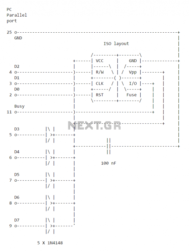
This simple PC Smartcard reader was shown in Electronics Design magazine February 17, 1997 issue on page 172 in the ideas for design section. The circuit is designed by Jose Carlos Cossio and is based on simple smartcard reader...
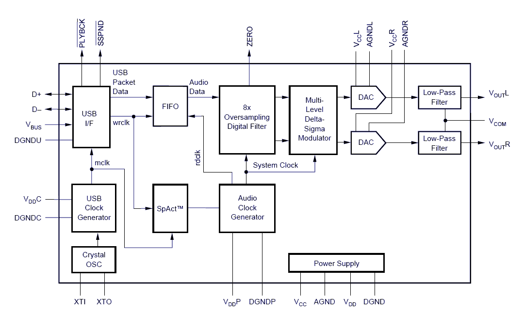
Designing and building a USB sound card is no longer a headache with the PCM2702 integrated circuit from Texas Instruments. The PCM2702 is a digital-to-analog converter (DAC) that features digital-to-analog output channels. The integrated interface controller of the PCM2702...