
Search Light Signal

The searchlight signal control circuit is designed to ensure proper indication of track occupancy and signal status through a combination of visual signals. The LM556 dual timer IC serves as the core component, providing the necessary timing and control functions to manage the operation of the red, yellow, and green LEDs. Each LED is configured to indicate the status of the block it controls, with the green LED indicating a clear block under normal circumstances, and under approach conditions, it only illuminates when the preceding block is red.
The circuit's flexibility allows for configuration changes to accommodate various operational scenarios, such as approach lighting versus normal lighting. The approach lighting configuration is particularly important for safety, as it ensures that the green signal is only displayed when it is safe for a train to proceed, based on the status of the subsequent block.
The capability to connect multiple signal blocks using a four-conductor cable enhances the modularity of the system, allowing for easy expansion and integration into larger signaling systems. The use of terminal blocks facilitates straightforward connections, ensuring reliable signal transmission between blocks.
The design also considers different power supply voltages and LED currents, allowing for customization based on specific operational requirements. The ability to adjust resistor values enables the circuit to be tailored for various LED brightness levels, accommodating different visibility conditions.
Incorporating optoisolators into the design allows for safe and effective control of the signal circuits, minimizing the risk of interference between multiple blocks. The use of diodes to isolate input devices enhances the circuit's functionality, allowing for complex control schemes that can accommodate multiple input sources without cross-talk.
Overall, this circuit provides a robust solution for managing signal indications in a railway or model train environment, ensuring that operators have clear and accurate information about track conditions while maintaining safety standards.This circuit controls a Searchlight type signal head and produces solid - RED, YELLOW or GREEN indications. The signals can be connected for NORMAL or APPROACH type lighting of the Green signal. The circuit uses a LM556 - Dual Timer IC in a complimentary output configuration to drive a red and green, bipolar type light emitting diode to produce t
he signal`s three colours. There are two complete block signal circuits on the PCB in the photo. The circuit on the left side is wired for APROACH lighting of the Green signal while the circuit on the right side is wired for NORMAL lighting of the Green signal. Schematics for both configurations are shown below. APPROACH - Type Lighting means that the GREEN signal is on only when the block after a particular signal is showing a RED signal.
The Green signal is on when Terminal GI is LOW. The YELLOW or RED input functions are the same as for Normal GREEN lighting. The next diagram shows five signal block circuits connected using the terminal blocks mounted on the circuit boards. A four conductor cable could be used to connect the individual blocks together. The signal circuits can be controlled by any device that can pass at least 1 milliamp current and shares a common connection with minus terminal of the signal circuit`s power supply.
The circuit is designed for a 12 volt power supply voltage and will drive light emitting diodes at approximately 10 milliamps. Other supply voltages and LED currents can be used by changing the values of certain resistors in the circuit.
- If the signal LEDs are too bright, external resistor can be connected at the circuit board`s outputs rather than replacing resistors R5 on the circuit board. The combined current from a DETECT INPUT of one block and the YELLOW INPUT from the previous block is about 2 milliamps.
This low current allows the PNP signal circuit to be controlled directly by optoisolators. More than one block can be controlled by a single input device if diodes are used to separate block input devices such as occupancy detectors, toggle switches and computer control systems. The 556 - Searchlight Signal Driver circuit can be controlled by many types of input devices including most Block Occupancy Detectors designs as well as toggle switches and the outputs of computer system interface cards.
For BODs with open collector transistor outputs, the signal circuit and the BOD can use the same power supply and must have a common connection at the minus of the power supply. Computer system interface cards usually have open collector transistor outputs. The interface card can have its own power supply but will need a common connection at the minus of the power supply of the card and the signals circuit.
A dispatcher can control the signals by using toggle switches to control the signals as shown on the block diagrams. In this case no occupancy detectors would be needed but they could be used in conjunction with the switches.
The next diagram shows how diodes can be used at the BOD inputs of the signals to provide more complex signal schemes. The diodes allow separate input devices to control more than one signal while isolating the BODs from each other during normal operation.
A possible use for diodes at the BOD inputs is at a rail crossing or interlocking where tracks that do not have the right-of-way would have their signals held at RED by the dispatcher until the crossing is clear. 🔗 External reference
Related Circuits
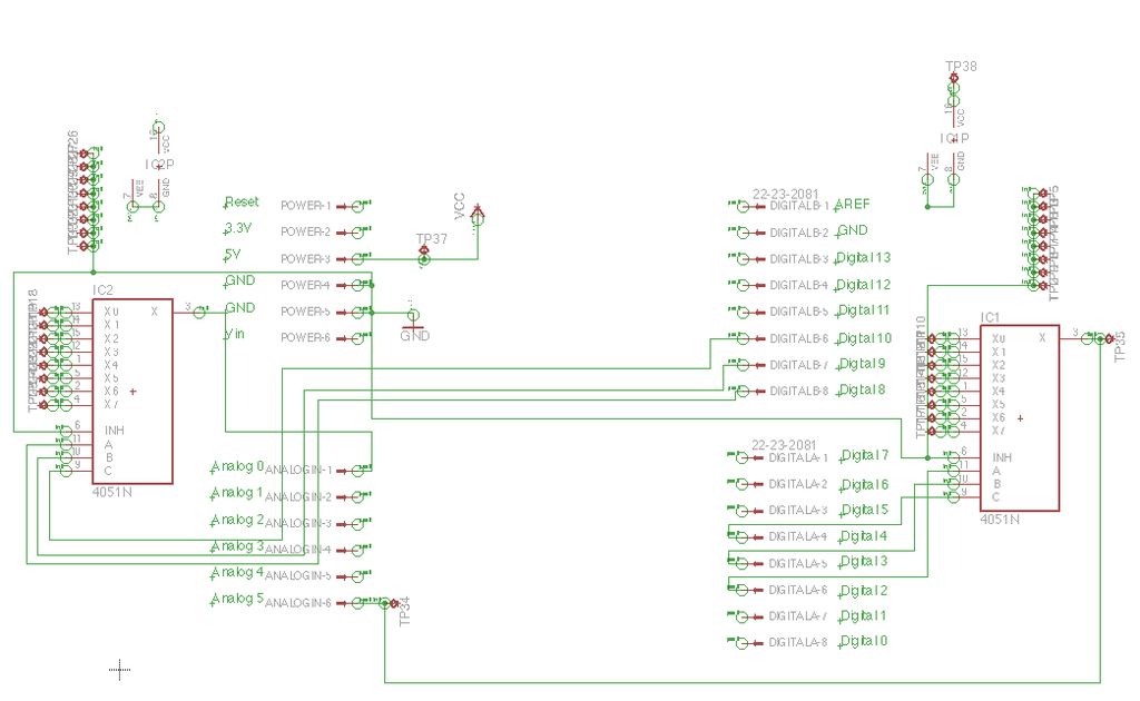
Inspired by a previous project, a unique design was developed that incorporates an umbrella capable of playing musical notes when pressed. For additional information regarding the 4051 chip, which functions as a multiplexer or demultiplexer, refer to resources available...
A simple and interesting project schematic for a cell phone signal-activated LED circuit. The circuit will illuminate an LED when a call is made from a cell phone. This cell phone signal-activated LED circuit utilizes a basic principle of detecting...
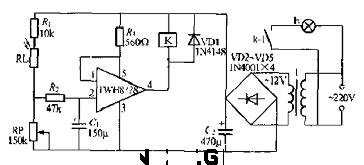
Automatic lights using a light sensor, the TWH87SL power switch integrated circuit consists of a first input terminal TWH8751 connected to the positive terminal of the power supply. The output pin state is determined by the strobe terminal, which...
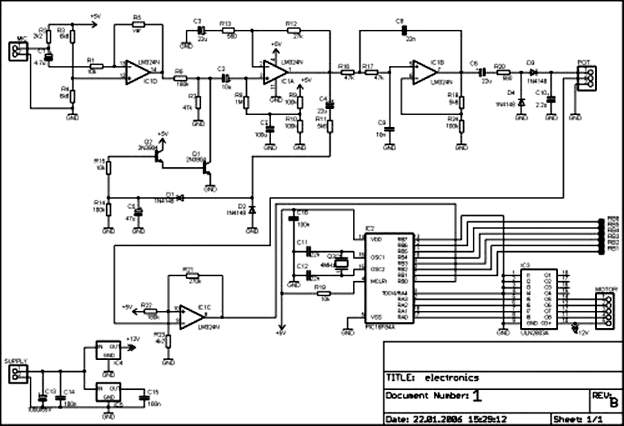
External circuit converts bass beat of music into pulses. The motor is controlled by them. If there's bass beat recognized then the motor rotates one direction (in full stepping) for a predefined time then stops. If the second beat...
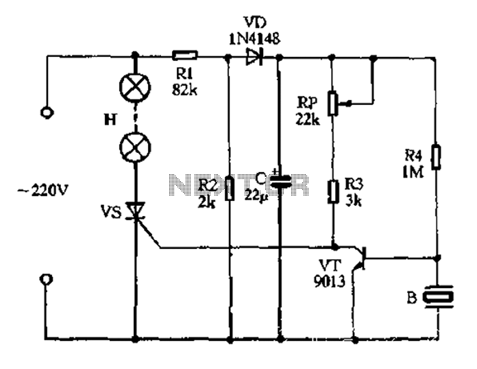
The circuit operates on 220V AC, utilizing resistors R1 and R2 to create a partial voltage drop. A VD half-wave rectifier converts this AC voltage to approximately 3V DC across capacitor C. An adjustment potentiometer RP is incorporated to...
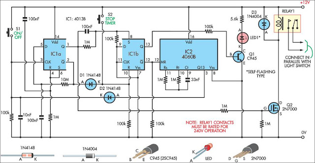
This 9-minute timer switch is designed to control lighting in a toilet or bathroom. The timer is activated by pressing switch S1 and deactivated by pressing S1 again. If the switch is not turned off, the light will automatically...