
Discolight using PIC16F84A


When programming the PIC16F84A, it is necessary to fill the first three EEPROM locations with the setting values. The values used are: 01 14 E0. The PIC is programmed with Ic-Prog using a simple JDM programmer.
After successfully building the whole hardware, it is necessary to adjust the trimmers very precisely. If adjustments are not experimented with several times, it is possible that the PIC will not recognize every beat due to the small amplification level, or it may perform several actions for only one beat. Therefore, finding the best adjustment is crucial. The original circuit that converts the bass beat into pulses is from Dan Fraser's Audio Trigger Circuit for light chasers, updated by Tomi Engdahl. The line-out control was replaced with a microphone, and the 555 circuitry was removed due to the software solution. The unique aspect of this project is the software for the PIC microcontroller.
The circuit employs a PIC16F84A microcontroller to process audio signals and control a stepper motor based on detected bass beats. The audio input is captured via a microphone, which converts sound waves into electrical signals. These signals are processed to identify bass beats, which trigger the motor's operation.
The motor operates in two stepping modes: full stepping and half stepping. Full stepping provides greater torque but less smoothness, while half stepping allows for smoother operation at the cost of reduced torque. The microcontroller implements a timing mechanism to determine the duration of motor rotation and the direction of rotation based on detected beats, with a random number generator influencing the number of rotations.
To ensure reliable operation, the system incorporates a debounce mechanism to prevent multiple triggers from a single beat detection. This is managed through a timing counter that disables further beat detection for a specified duration after the first detection. The system is designed to save configuration settings in EEPROM, ensuring that adjustments are retained even after power loss.
User adjustments are facilitated through trimmer potentiometers, allowing for fine-tuning of the circuit's sensitivity and response characteristics. This flexibility is essential for accommodating different audio environments and ensuring optimal performance.External circuit converts bass beat of music into pulses.The motor is controlled by them. If theres bass beat recognised then the motor rotates one direction(in full stepping) for a predefined time then stops. If the second beat comes in then it rotates again for the same time and so on.There is a random number generator (from 1 to 4) written into the code which tells how many times have the motor to rotate one direction.After that the PIC changes rotation direction of the motor.If the tempo is too fast (<400msec) then the direction is changed immediately.
When the motor stops after the predefined time period a counter is enabled.if beat doesnt come in for 15sec the motor starts to rotate slowly in half stepping. If a beat comes in the counter is disabled and the motor continues its normal rotation in full stepping. Half stepping is smoother but unfortunately the torque is less) The PIC can control the motor after every beat or its possible to bypass some beats.It can be done by pushbuttons.
Rotation speed and rotation lenght can be adjusted too.Settings are limited between values to prevent possible register overflow-underflow. These values are saved in EEPROM so after shut-down the settings dont lost. A beat consist of a series of vibrations(dont know the correct english word for that-sorry) so the PIC gets a few interrupts.To prevent multi-triggering theres a counter written into the code which disables reaction to beat for 200msecs after the first interrupt.
180msec delay is enough if you are using amplifiers output (or line out) as music source. I had to increase it to 200msec because i use microphone and the rooms echo influences operation. Programming the PIC - Adjustments When programming the PIC16F84A you need to fill the first three EEPROM locations with the setting values. I used these one: 01 14 E0 I programmed the PIC with Ic-Prog using a simple JDM programmer. Download Source Code After you succesfully built the whole hardware you need to adjust the trimmers very precisely.
If you dont experiment a few times with adjusting them then its possible that the PIC will not recognise every beat because of the small amplifycation level. Or,it will do several things at only one beat.So you have to find the best adjustment. The original circuit which converts bass beat into pulses is from Dan Frasers Audio trigger circuit for light chasers.
(updated by Tomi Engdahl). I only replaced the line-out control with microphone and removed the 555 circuitry because of the software solution. The very-own in this project is the software for the PIC microcontroller. 🔗 External reference
Related Circuits
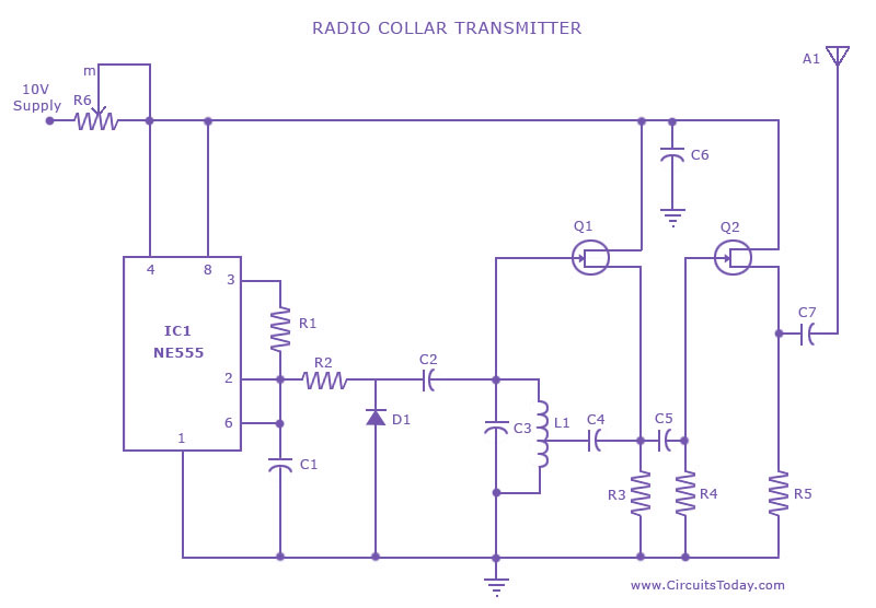
This is a radio transmitter circuit diagram designed for integration into radio collars using the NE 555 integrated circuit. The circuit transmits a pulse in the FM band, specifically between 88 MHz and 105 MHz. The radio transmitter circuit utilizes...

This is the design circuit diagram of an ultrasonic mosquito repeller. The circuit operates based on the theory that insects, such as mosquitoes, can be repelled by sound frequencies in the ultrasonic range (above 20 kHz). The circuit utilizes...
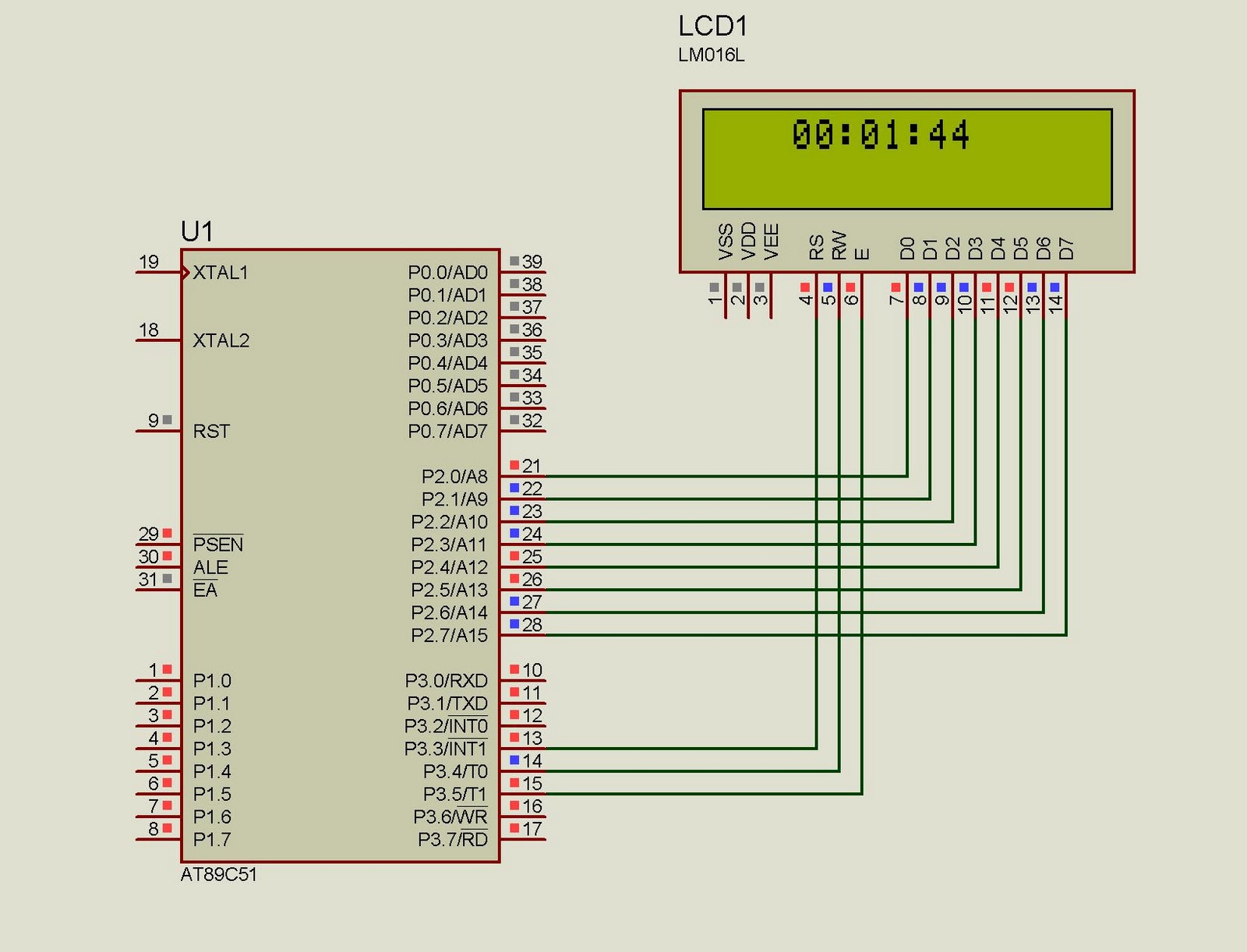
This project implements a real-time clock using the 89C51 microcontroller. The clock's data format is hours:minutes:seconds, which is displayed on a 16x2 LCD. The code has been tested and compiled using the Keil uVision compiler. The circuit diagram for...
Using modulated rectangular waves of different time periods, the circuit presented here produces ringing tones similar to those produced by a telephone. The circuit requires four astable multivibrators for its working. Therefore, two 556 ICs are used here. The...
Power an RS232-TTL converter circuit using the serial port to eliminate the need for an external power supply. It has been noted that the DTR, RTS, and TD pins can facilitate this. Since the TD pin is already utilized...
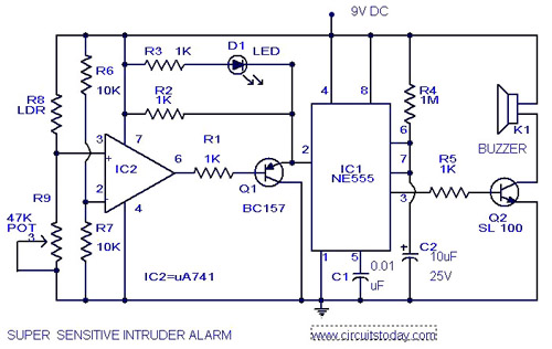
The circuit diagram represents an ultra-sensitive intruder alarm. A shadow from an intruder passing nearby is sufficient to trigger the alarm. The operational amplifier IC2 (uA 741) is configured as a sensitive comparator, with its set point determined by...