
infrared beam proximity detector

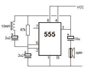
The circuit operates by utilizing an infrared (IR) beam for detection, which can serve dual purposes: an infrared beam barrier and a proximity sensor. At its core, it employs a Sharp IR module or a Vishay equivalent, which is responsible for receiving the infrared light emitted from a pair of LEDs. The design includes a 555 timer integrated circuit (IC) configured as an oscillator, generating a frequency of approximately 38 kHz, adjustable between 36 kHz and 40 kHz using a 10K potentiometer. This frequency modulation is essential for maintaining effective communication between the transmitter and receiver while minimizing interference from ambient light sources.
The duty cycle of the emitted IR beam is set to about 10%, which is crucial for enhancing the range of the system. By allowing more current to flow through the LEDs during the 'on' phase, the system can project a stronger IR signal. The receiver's output is linked to a relay, which serves as a switch to activate or deactivate connected devices such as alarms or lights based on the presence or absence of the IR beam.
In its proximity detection configuration, the LEDs must be aligned with the IR module and oriented at the same height. The design suggests encasing the LEDs in reflective materials like glass or aluminum foil to concentrate the IR beam and prevent dispersion. This configuration ensures that when no object is present, the IR beam does not reach the receiver, keeping the circuit inactive. Conversely, when an object approaches, the emitted IR light reflects off the object and is detected by the IR module, triggering the relay and activating the output.
For improved reliability and to reduce false triggering, it is recommended to replace the standard 0.47 µF capacitor with a larger 1 µF capacitor or higher if necessary. This adjustment can help stabilize the circuit's response to varying distances and environmental conditions, thereby enhancing the overall functionality of the infrared detection system.his circuit can be used as an Infrared beam barrier as well as a proximity detector. The circuit uses the very popular Sharp IR module (Vishay module can also be used). The pin nos. shown in the circuit are for the Sharp & VIshay modules. For other modules please refer to their respective datasheets. The receiver consists of a 555 timer IC working as an oscillator at about 38Khz (also works from 36kHz to 40kHz) which has to be adjusted using the 10K preset. The duty cycle of the IR beam is about 10%. This allows us to pass more current through the LEDS thus achieving a longer range. The receiver uses a sharp IR module. When the IR beam from the transmitter falls on the IR module, the output is activated which activates the relay and de-activated when the beam is obstructed. The relay contacts can be used to turn ON/OFF alarms, lights etc. The 10K preset should be adjusted until the receiver detects the IR beam. The circuit can also be used as a proximity sensor, i.e to detect objects in front of the device without obstructing a IR beam.
For this the LEDs should be pointed in the same direction as the IR module and at the same level. The suggested arrangement is shown in the circuit diagram. The LEDs should be properly covered with a reflective material like glass or aluminum foils on the sides to avoid the spreading of the IR beam and to get a sharp focus of the beam. When there is nothing in front of them, the IR beam is not reflected onto the module and hence the circuit is not activated.
When an object comes near the device, the IR light from the LEDs is reflected by the object onto the module and hence the circuit gets activated. If there still a lot of mis-triggering, use a 1uF or higher capacitor instead of the 0.47uF. 🔗 External reference
Related Circuits

The transmitter provides an optical link (infrared) for headphones. Three infrared LEDs (IR) are powered by T1, with P1 used to adjust the current level. The current consumption of this headphones infrared transmitter is approximately 60mA at 9V. The infrared...

IC1 and IC2 form an inverting half-wave precision rectifier and peak detector circuit. Negative input signals that swing with peaks larger than the voltage on C1 cause this capacitor to charge to the new peak voltage. The capacitor retains...

This is a simple alarm circuit that produces a musical tone when water or any conductive liquid comes into contact with the two sensor wires provided. The circuit utilizes four transistors and one melody generator IC (M3482). When water...
A wideband RF detector is being designed, utilizing a series of resonant LC tanks spaced between 5 to 10 MHz apart, with an exception of 1 MHz spacing from 9 MHz onwards. The design of a wideband RF detector incorporating...
A very simple metal detector electronic project can be designed using a simple 555 timer integrated circuit. As you can see in the schematic circuit, this electronic project requires few external electronic parts. This circuit detects metal and also...

A simple ionization smoke detector with interconnect and timer alarm circuit can be constructed using the A5367 low-current, CMOS circuit, which provides all essential features for an ionization-type smoke detector. This CMOS IC, manufactured by Allegro MicroSystems, includes interconnect...